In this article I’ll be taking a look at the CAN bus network in a 2009 Ducati 848. How to find the bus, confirm the high and low lines with a scope and analyse messages with a Linux box and socket-CAN. The aim of the game is to identify a way to get onto the bus, and then analyse the messages going across the bus. We’ll end up figuring out how to log the throttle position and RPM data, how the immobilizer is implemented and how to bypass it.
The Controller Area Network (CAN) is a communication mechanism used in the automotive industry (among others) allowing devices to broadcast messages. In the case of the Ducati, the CAN bus is used for communication between the ECU and dashboard. If you’re already familiar with CAN bus hacking, then this post likely wont reveal anything ground breaking for you. Bit of revision never hurt anyone though :D
A note on logical hacking
For this kind of project, where the thing that you’re trying to hack is expensive and you’ve only got one, I’ve found that relying on logic and building a solid understanding of the system prior to doing any actual hands-on hacking is a great way to avoid potential headaches and hash out potential exploits early on. Think of it like a design-review with no design.
For example, we know that the bike uses CAN bus because the factory workshop manual tells us so. The manual explains the relationship between the dashboard and the main ECU, and which sensors terminate where. Doing some digging regarding replacement keys for an 848, we can quickly determine that the keys and the dashboard are linked somehow (the owners manual goes into detail about programming additional keys into the dash). Following the wiring diagram, the immobilizer antenna connects to the dash, however the starter button goes to the main ECU. Therefore, there needs to be some mechanism for the dashboard to communicate the immobilizer state to the ECU.
By reading the factory manual and asking some pointed questions at the local Ducati dealership, you can build a solid idea of how the technical side of an exploit might work before putting any tools on the bike. In this case, I suspect that there is a CAN bus message that is sent from the dashboard to the ECU to disable the immobilizer. Turns out that was right-ish. I’ll touch back on this more later in this article.
Tools
The tools used in this article are all firmly in the cheap-and-cheerful category. I’ll be using a standard multimeter, a Hantek 6022BL oscilloscope with Open Hantek software, and an 8 Devices USB2CAN CAN bus adapter. I’ve had some poor experiences with the Arduino based CAN bus interfaces, specifically with messages getting lost. My usual go-to these days is the 8 Devices USB adapter for reversing work with the laptop, or a PICAN2 on a Raspberry Pi for things like data logging while riding.
On the OS side of things, everything in this article was done on an Ubuntu 18.04 install.
Finding the CAN bus
So looking at the wiring diagram, finding the CAN bus lines between the ECU and the dash is a fairly trivial process. However, why unnecessarily splice wires and remove the seven million bolts that hold the fairings onto the 848? Instead, I decided to take a look at the Ducati Data Analyzer port underneath the pillion seat:
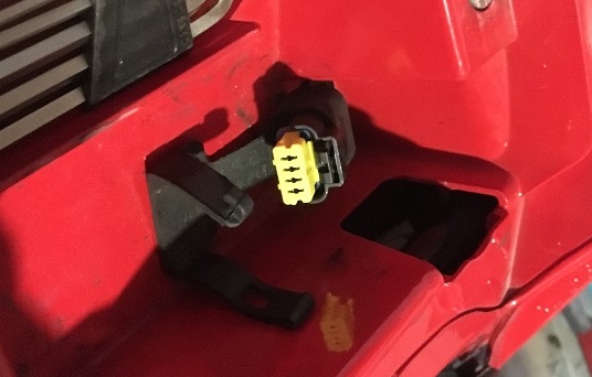
Sticking to the whole ‘logical hacking’ schtick, it makes sense that the data logging unit would live on the CAN bus. The unit is designed to record throttle position, RPM, etc. All of that information is usually available via other CAN connected devices. So, surely, the Ducati data analyzer will leverage this.
Looking at the DDA port above, we can see four pins. Turning the key and checking those with a multimeter we get the following:
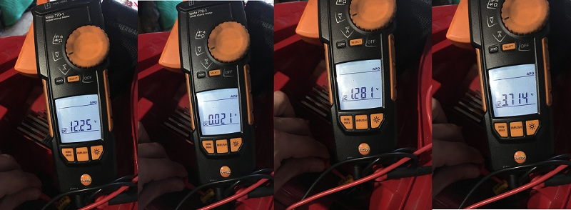
- pin 1 - 12v (battery voltage)
- pin 2 - ground
- pin 3 - 1.2V
- pin 4 - 3.7V
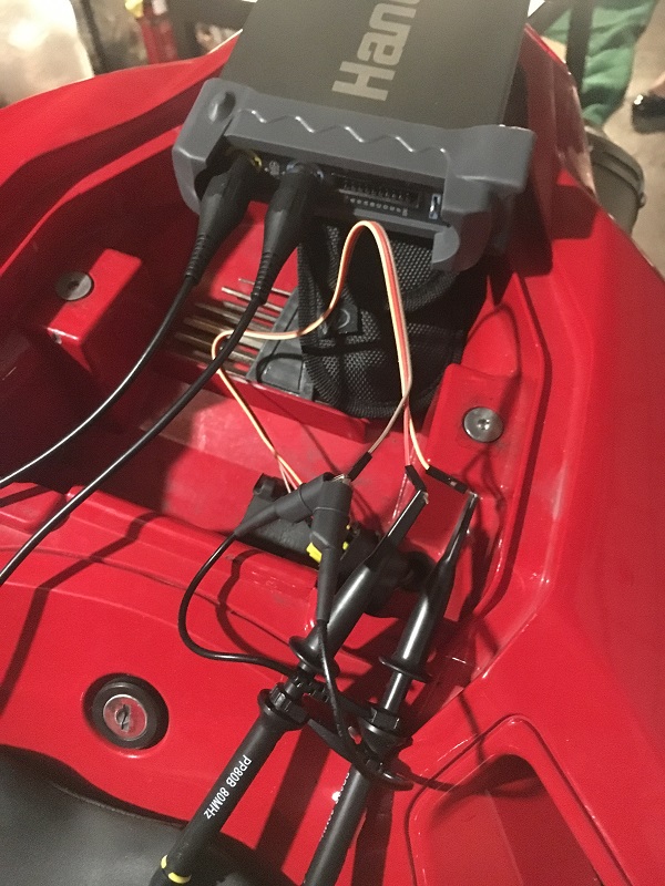
Next, we take a look at pin 3 and pin 4 with the oscilloscope, which reveals pin 3 as CAN-H and pin 4 as CAN-L:
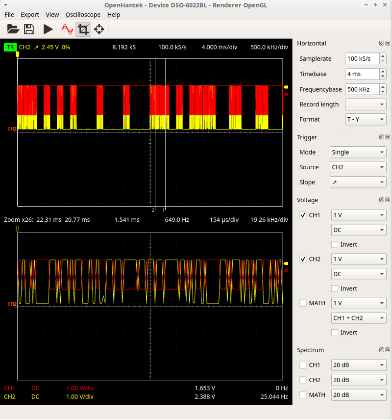
This, indeed, is a CAN bus network, but a weird CAN bus network. The bike is using a fault-tolerant ISO 11898-3 network. The following image shows what a “normal” CAN waveform looks like (thanks Wikipedia):

Fault-tolerant CAN isn’t a huge problem. Thankfully, you can happily read fault-tolerant CAN messages with a standard CAN bus adapter (at least those with an MCP2551 transceiver). Unfortunately, you won’t be able to send messages without a fault tolerant transceiver, but for message logging the standard CAN adapter will work just fine.
The last thing we need to know before attaching the adapter is the network speed. ISO 11898-3 is supported up to 125KBPS, and that’s whats in use here. You can attempt trial-and-error, but a more robust solution is to hook up a logic analyzer (the Hantek 6022BL is supported by Salae Logic), and look at the time taken for a single bit transmission. You can probably achieve this with just the oscilloscope, but I have a logic analyser. Smoke ‘em if you got ‘em, right?
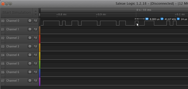
1 bit takes 8 microseconds. 1/0.000008 and hey presto, you know the bit-rate. In this case, 125KBPS.
So, butchering a Cisco rollover cable (handy pin-out here) and connecting the 8Devices USB2CAN interfaces lets us see whats happening on the bus:
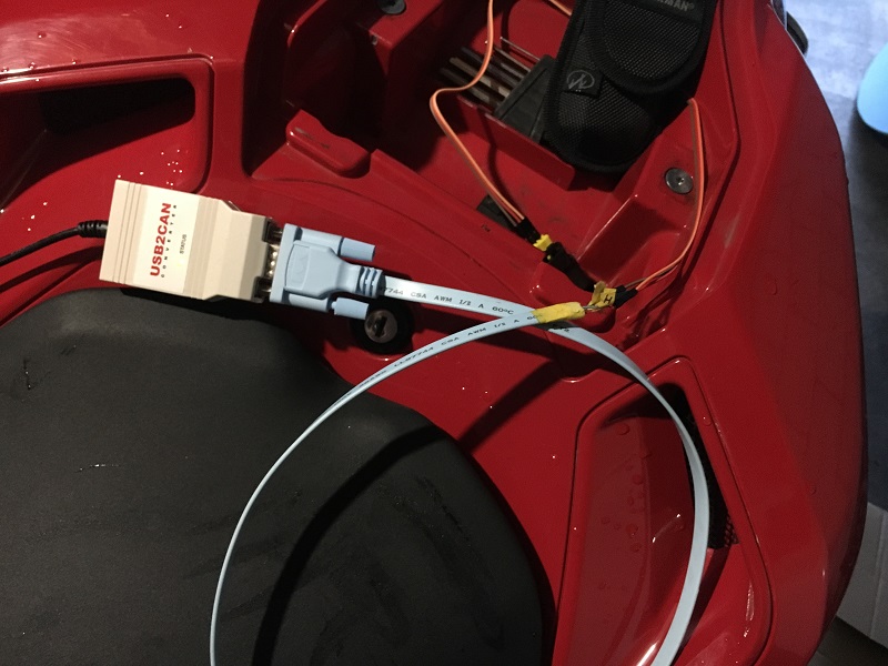
The GIF above, I’m running the candump command on the can0 interface, after setting it to 125KBPS.
Message Logging
So the two main goals are to identify the throttle position and RPM data, and to figure out how the immobilizer messaging is working. We’ll tackle the TPS/RPM first.
Identifying TPS/RPM
Logging throttle position and RPM is useful when attempting to figure out how the ECU is behaving under certain conditions. Log this information with something like a raspberry pi, add in wide-band O2 sensor information and you end up with a pretty powerful portable tuning setup.
With the 8 Devices USB2CAN interface wired into the bike, I’ll run the cansniffer command. This utility gives a good visual representation of the messages going across the bus, highlighting changes bytes. With the key on and the engine off, I roll the throttle back and forth and see the following:
The above message reveals message 0x80, byte 5 as the TPS info. The value was 0x00 at closed throttle and 0xC8 at wide open.
Finding the RPM information is much the same process as above. This time, I start the bike and proceed to rev the engine, looking for changes in the CAN messaging.
You can see the RPM data above in message 0x80, bytes 3 and 4. The bytes are hovering around 0x05C0 range usually, which translates to 1472 RPM (or the bikes idle RPM). There were a few minor throttle blips that you can see going on above. I wasn’t too keen on pinning the bike to the limiter after hours, especially with the open pipes!
After spending some time with cansniffer, we’ve established that both the TPS and RPM data is available in the 0x80 message.
Immobilizer messaging
My theory with the immobilizer was that the immobilizer information is somehow sent from the dashboard to the ECU via the CAN bus. To test this, I decided to dump the bus messages during an immobilizer fail condition (by unplugging the transponder antenna) and during a successful boot, then diff the messages in the two files.
The message dumps were taken with the following candump command:
# run dump, turn key
candump can0 | tee boot_1.candump.txt
# unplug tranponder antenna, run dump, turn key
candump can0 | tee boot_immofail.candump.txt
My first instinct was a specific CAN bus message ID for the immobilizer-disable function. Unfortunately, there was no unique message ID in the successful boot file!
doi@asov:~$ head boot_1.candump.txt
  can0  080   [8]  00 00 00 00 00 00 C8 00
  can0  080   [8]  00 00 00 00 00 00 C8 00
  can0  100   [8]  00 00 00 00 00 22 04 00
  can0  080   [8]  00 00 00 00 00 00 C8 00
  can0  080   [8]  00 00 00 00 00 00 C8 00
  can0  080   [8]  00 00 00 00 00 00 C8 00
  can0  080   [8]  00 00 00 00 00 00 C8 00
  can0  080   [8]  00 00 00 00 00 00 C8 00
  can0  100   [8]  00 00 00 00 00 22 04 00
  can0  080   [8]  00 00 00 00 00 00 C8 00
doi@asov:~$ awk {'print $2'} < boot_1.candump.txt  | sort -u > messages_1
doi@asov:~$ awk {'print $2'} < boot_immofail.candump.txt  | sort -u > messages_2
doi@asov:~$ diff messages_1 messages_2
doi@asov:~$ # :-/
So the next step would be to see what data in those IDs changes, as the immobilizer flag is potentially serialized into one of the messages. Looking at which messages were unique in each state lead to a number of potential message candidates
doi@asov:~$ sort boot_1.candump.txt > boot_1_sorted.txt
doi@asov:~$ sort boot_immofail.candump.txt > boot_immofail_sorted.txt
doi@asov:~$ uniq -c boot_immofail_sorted.txt | sort -n
      1   can0  020   [8]  3E D8 40 00 00 00 00 00
      1   can0  020   [8]  3F D7 40 00 00 00 00 00
      1   can0  028   [8]  C8 3F A6 00 00 00 00 00
      3   can0  200   [8]  5A 7C 34 13 00 00 00 00
      6   can0  200   [8]  5A 7A 34 13 00 00 00 00
     11   can0  200   [8]  5A 7D 34 13 00 00 00 00
     17   can0  200   [8]  5A 79 34 13 00 00 00 00
     25   can0  200   [8]  5A 7E 34 13 00 00 00 00
     76   can0  200   [8]  5A 7B 34 13 00 00 00 00
     99   can0  029   [8]  00 00 00 00 00 00 00 00
     99   can0  300   [8]  74 00 62 9F 00 00 00 00
    138   can0  210   [8]  00 00 00 00 00 00 00 00
    138   can0  280   [8]  20 20 20 44 4F 4E 54 20
    139   can0  290   [8]  44 49 45 20 20 20 20 00
    488   can0  020   [8]  3E D7 40 00 00 00 00 00
    489   can0  028   [8]  C8 3F A6 30 00 00 00 00
    691   can0  100   [8]  00 00 00 00 00 22 04 00
   3456   can0  080   [8]  00 00 00 00 00 00 C8 00
doi@asov:~$ uniq -c boot_1_sorted.txt | sort -n
      1   can0  020   [8]  3E D8 00 00 00 00 00 00
      1   can0  028   [8]  C8 3F A6 00 00 00 00 00
      3   can0  200   [8]  5B 7C 34 13 00 00 00 00
      5   can0  100   [8]  00 00 00 00 00 26 04 00
      6   can0  020   [8]  3E D7 40 00 00 00 00 00
      7   can0  200   [8]  5B 7A 34 13 00 00 00 00
     12   can0  200   [8]  5B 7D 34 13 00 00 00 00
     15   can0  200   [8]  5B 79 34 13 00 00 00 00
     15   can0  200   [8]  5B 7E 34 13 00 00 00 00
     29   can0  200   [8]  5B 7B 34 13 00 00 00 00
     51   can0  029   [8]  00 00 00 00 00 00 00 00
     51   can0  300   [8]  73 80 62 9F 00 00 00 00
     81   can0  210   [8]  00 00 00 00 00 00 00 00
     81   can0  280   [8]  20 20 20 44 4F 4E 54 20
     81   can0  290   [8]  44 49 45 20 20 20 20 00
    244   can0  020   [8]  3E D7 00 00 00 00 00 00
    250   can0  028   [8]  C8 3F A6 30 00 00 00 00
    402   can0  100   [8]  00 00 00 00 00 22 04 00
   2040   can0  080   [8]  00 00 00 00 00 00 C8 00
doi@asov:~$ comm -23 boot_immofail_sorted.txt boot_1_sorted.txt  | uniq
  can0  020   [8]  3E D7 40 00 00 00 00 00
  can0  020   [8]  3E D8 40 00 00 00 00 00
  can0  020   [8]  3F D7 40 00 00 00 00 00
  can0  028   [8]  C8 3F A6 30 00 00 00 00
  can0  029   [8]  00 00 00 00 00 00 00 00
  can0  080   [8]  00 00 00 00 00 00 C8 00
  can0  100   [8]  00 00 00 00 00 22 04 00
  can0  200   [8]  5A 79 34 13 00 00 00 00
  can0  200   [8]  5A 7A 34 13 00 00 00 00
  can0  200   [8]  5A 7B 34 13 00 00 00 00
  can0  200   [8]  5A 7C 34 13 00 00 00 00
  can0  200   [8]  5A 7D 34 13 00 00 00 00
  can0  200   [8]  5A 7E 34 13 00 00 00 00
  can0  210   [8]  00 00 00 00 00 00 00 00
  can0  280   [8]  20 20 20 44 4F 4E 54 20
  can0  290   [8]  44 49 45 20 20 20 20 00
  can0  300   [8]  74 00 62 9F 00 00 00 00
doi@asov:~$ comm -23 boot_1_sorted.txt boot_immofail_sorted.txt  | uniq
  can0  020   [8]  3E D7 00 00 00 00 00 00
  can0  020   [8]  3E D8 00 00 00 00 00 00
  can0  100   [8]  00 00 00 00 00 26 04 00
  can0  200   [8]  5B 79 34 13 00 00 00 00
  can0  200   [8]  5B 7A 34 13 00 00 00 00
  can0  200   [8]  5B 7B 34 13 00 00 00 00
  can0  200   [8]  5B 7C 34 13 00 00 00 00
  can0  200   [8]  5B 7D 34 13 00 00 00 00
  can0  200   [8]  5B 7E 34 13 00 00 00 00
  can0  300   [8]  73 80 62 9F 00 00 00 00
Message ID 0x20 looked plausible, so I compared the 0x20 messages in each file.
doi@asov:~$ grep 020 boot_1.candump.txt  | uniq -c
      6   can0  020   [8]  3E D7 40 00 00 00 00 00
    111   can0  020   [8]  3E D7 00 00 00 00 00 00
      1   can0  020   [8]  3E D8 00 00 00 00 00 00
    133   can0  020   [8]  3E D7 00 00 00 00 00 00
doi@asov:~$ grep 020 boot_immofail.candump.txt  | uniq -c
     21   can0  020   [8]  3E D7 40 00 00 00 00 00
      1   can0  020   [8]  3F D7 40 00 00 00 00 00
    416   can0  020   [8]  3E D7 40 00 00 00 00 00
      1   can0  020   [8]  3E D8 40 00 00 00 00 00
     51   can0  020   [8]  3E D7 40 00 00 00 00 00
That looks promising, that third byte is 0x40 at the beginning of the successful boot, but quickly becomes 0x00. In the immobilizer failure scenario, the byte stays as 0x40. 0x40 translates to 0100 0000 in binary. A single bit, an immobilizer bit! Unsetting that bit allows the bike to start.
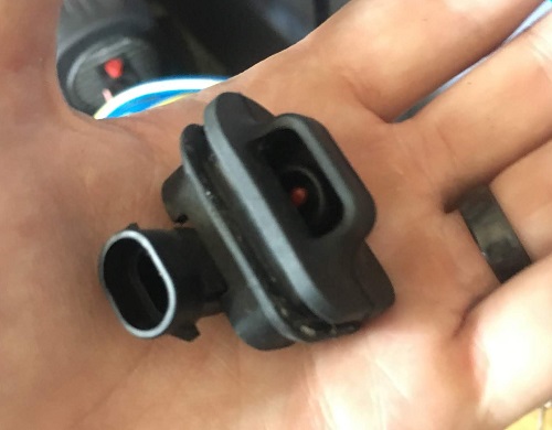
But first, I wanted to confirm the other two parameters. The first data byte (0x3E) corresponds to the ambient air temperature (minus 40, so 22 degrees celsius in the case above). The workshop manual shows the ambient air temp sensor connecting to the dashboard, so it makes sense that the dash would read that sensor and transmit the information to the ECU. This is what the temp sensor looks like, it sits underneath the dash:
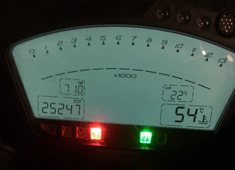
The temperature information is also displayed on the dashboard:
Confirming this hypothesis was a simple case of running candump and poking the ambient air temp sensor (human > ambient-air-temp, after all):
As the sensor warmed up, 0x3E turned to 0x3F, which also lined up with what was displayed on the dash.
I’m assuming the second data byte is the barometric data, given that sensor is built into the dash. Unfortunately, I couldn’t think up a way of raising or lowering the air pressure in my garage at the time.
Ducati also implement a code card. The code card contains a printed 6 digit number that can be entered into the dash via the hand controls. When the immobilizer fails, the bike gives you the option to enter a code. After doing all the diffing above, I tried the same can sniffer technique used for the RPM and TPS analysis, but when punching in the code. After the correct code is entered, the 0x40 turns to 0x00, just like when the transponder handshake is successful. In retrospect, this would have been a much faster approach from the get go.
TLDR: the third data byte in message 0x20 contains the immobilizer flag. Entering the code, or having a valid transponder key, unsets this flag.
Immobilizer bypass
At this point, immobilizer bypass is a case of wiring up a fault-tolerant CAN bus interface and transmitting message id 0x20 with the immobilizer flag disabled. Behold, fault-tolerant CAN bus interface.

As long as the device transmits the valid information at a greater rate than the dash, no problem. If you’re attending Kiwicon 2018, I’ll be demoing this live on stage. The Artisinal Hand-Wired POC-o-tron simply broadcasts message 0x20 with the data 0x34 0xD9 0x00 0x00 0x00 0x00 0x00 0x00.
SAFETY NOTE: This is a POC immobilizer bypass mechanism to demonstrate CAN bus message injection. If the immobilizer bit is reset (or your Arduino dies), the engine will shut off. I suggest against riding the bike in this state. If you are looking to permanently disable the immobilizer then do so by unsetting the appropriate flag in the ECU firmware.
Summary
Hopefully this article has shed some light on the process of finding and interacting with a vehicle’s CAN bus. Aside from the use of a fault tolerant network, this specific instance was particularly painless given the way Ducati have set up the data logger port. If your application isn’t as helpful, then start with wiring diagram in one hand, scope in the other, and go from there!
There is a huge wealth of information on interacting with CAN bus networks on the internets, success is likely only a google search away. You’ve got this.