This article is a follow up to Part I - Practical CANBUS Reversing – Understanding the Ducati Monster. We’ll look at implementing the protocols from Part I using an aftermarket ECU, pulling some starting fuel and ignition map data out of the factory ECU through the chip debugging interface and we’ll talk about a few of the things I learned along the way.
I’ll be covering some of this junk in person at Kawaiicon in a few weeks. As per usual, I have grossly overestimated how much content I can fit into 30 minutes worth of conference talk. This article is intended to cover some of the nitty-gritty that’ll be mostly hand-waved away in the talk.
Once again, a safety warning. Messing with vehicles is dangerous, may void your warranty and can lead to people getting hurt. Please exercise caution and accept that this article is intended only to tell you a story of how I approached this project.
In the last post, the CANBUS communication between the dashboard and the factory ECU were reversed, and we figured out how the ABS module signals work. We now need to wire in the aftermarket ECU, configure it to spit out the right CANBUS data and find some sensible starting values for fuel and ignition maps.
ECU Selection and Wiring
Looking at the CANBUS data from the original article, the Ducati did not seem to use any kind of standard protocol that is supported out-of-the-box by most ECU manufacturers, meaning I needed to find something that allowed user-configurable arbitrary CANBUS messaging inputs and outputs. I settled on a MaxxECU Street due to the CANBUS configuration and number of inputs. The Street uses the same Molex connector as the factory Siemens ECU, which is a happy coincidence. This means I could re-pin the connector in the right order for the MaxxECU, rather than have to crimp all new pins.
The more gear-head readers are probably wondering about the injector and ignition coil arrangement, since the MaxxECU requires logic-level coil triggers. The coils were replaced with LS style D585 coils. Thankfully, the Ducati uses a standard Pico style fuel injectors so I picked up some Bosch injectors which came with dead-time and flow data. Accurate dead-time time and flow information is not strictly necessary, but it helps the volumetric efficiency values in the fuel tables reflect reality by feeding accurate information into the fuel-load calculation.
With that, it was time to cut apart the wiring loom, delete the unused circuits (like the narrow band O2 sensors and external MAP sensor), tweak the power circuit for the ECU, add in a starter relay, and wire in the new connector. I ordered some new pins for the various connectors from mouser and got to work:
After going through the above, modifying the stock loom took about as long as making one from scratch. If I was doing this again, I think I’d bite the bullet and make a new one. Or leave the loom completely stock and make up an adapter PCB and harness to connect the aftermarket ECU to an unmodified loom.
With everything done, the bike was pulled apart, a wide-band O2 sensor bung welded into the exhaust collector and the new loom installed. Did the new ECU fit in the stock location? Of course not, that would be too easy.
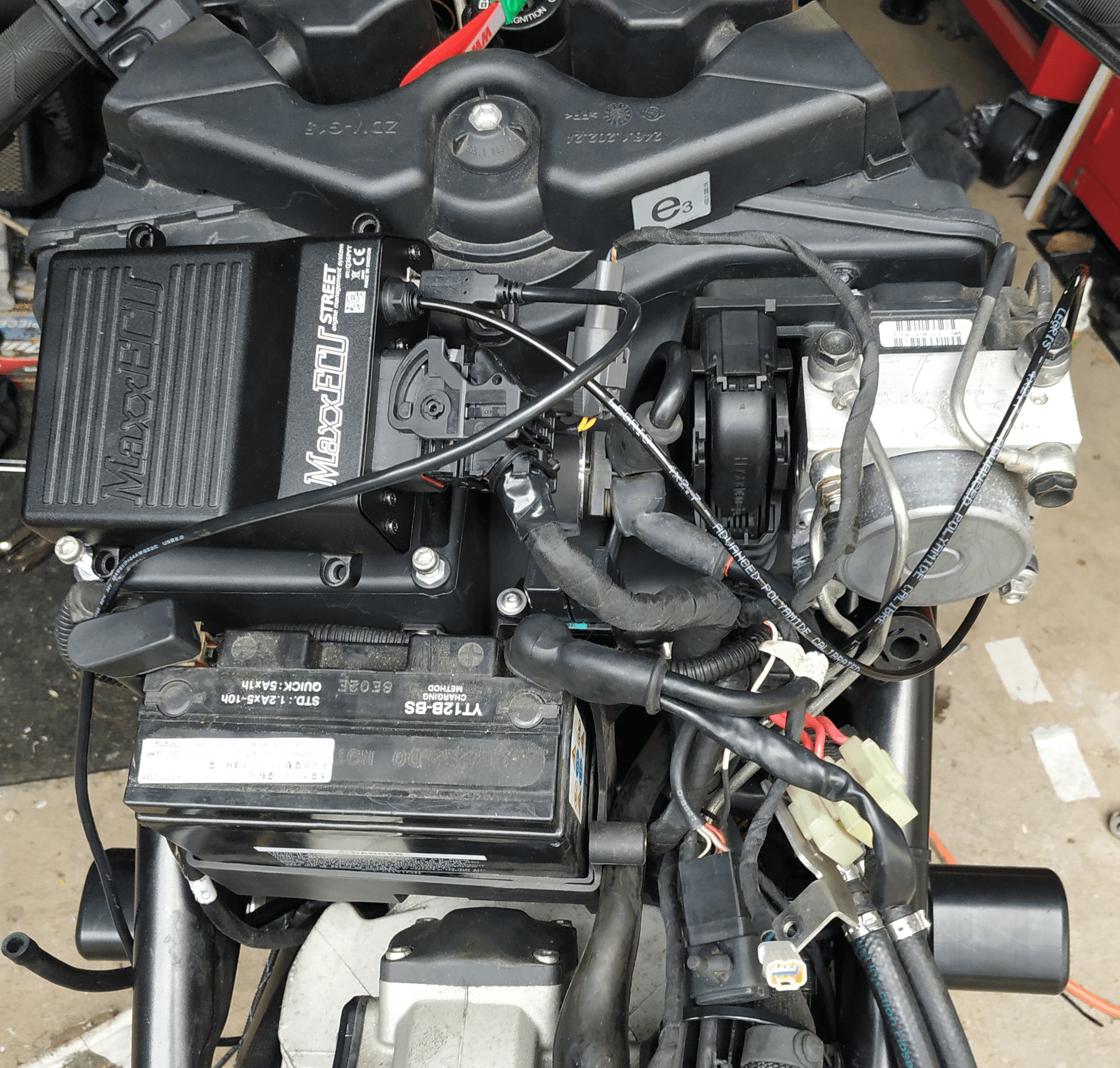
The solution here was to delete the air box and make up a bracket to hold the ECU, which I wasn’t thrilled about. One of my Pulse colleagues was kind enough to 3D print some velocity stacks from carbon fiber reinforced nylon which, along with some Pipercross sock filters, sorted out the intake system. You can see the bracket design in the CAD drawing below, this was laser cut out of 3mm aluminium and then bent up.
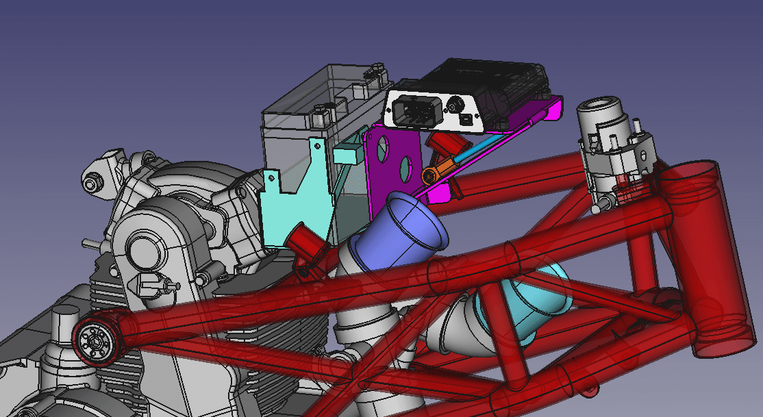
You can see one of the filters hiding behind the frame here:

After some testing to make sure the circuits were working as expected, I could move onto the ECU configuration. I’ll skip over the straight forward input/output stuff since the Ducati sensor and switch package isn’t anything particularly interesting. Lets skip right ahead to…
CANBUS Configuration
This is the part where we can put the spec from Part I into practice. This means going through the MaxxECU functionality and spitting out the relevant data for each message. If the CANBUS configuration is done properly, I can use this new aftermarket ECU with no change to the factory dashboard.
Outputs
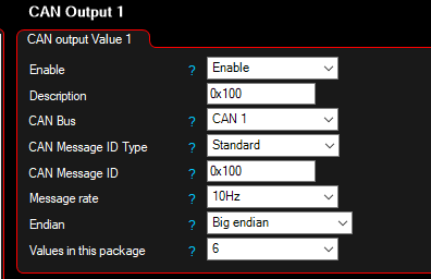
The ECU needs to output four messages. 0x100, containing RPM and vehicle speed data, 0x211 containing engine temperature, intake air temperature and battery voltage, and 0x280 and 0x290 containing the startup message and localisation byte. 0x280 and 0x290 are simple hard coded byte data, so I’ll skip that one here.
Lets go through configuring the other two messages:
0x100
A quick refresher from Part I, here is what we need to implement. The ECU needs to broadcast the following CANBUS messages and data:
100#E0040005DC210001
    ┌───- │   │ │ │
    │     │   │ │ │
    │     │   │ │ └─Killswitch on/off (optional)
    │    RPM  │ │
    │         │ └──Shift light
   VSS + Gear │    0xC0 Slow
    │         │    0x80 Fast
    │         │    0x40 Solid
    │         │
    │         └────ABS Light + extras
    │
    1110 0000 0000 0100
    ───-───────────────
    Gear  Vehicle Speed


0x21 - 0010 0001
       │ │     │
       │ │     └───Run
       │ │
       │ └─────────ABS Light
       │
       └───────────Starter button
The CANBUS functionality in the MaxxECU lets us manually build and manipulate CANBUS data, which is the reason it was selected for this project.
After setting up the number of values and the message rate, we can configure each of the fields:
The RPM is easy, it’s just the RPM value. Since the first two bytes include both the vehicle speed and the neutral light information, a math channel is set up to provide that data. The values here are set up to stuff the neutral light information into the right bit positions in the resulting 16-bit integer:
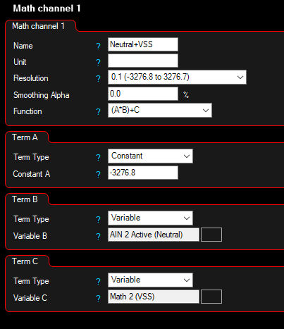
Math 2 is set up to convert the KM/H vehicle speed that the ECU understands to a value that the dashboard expects. I played around with different hard-coded values in Term A and observed the dashboard to figure out the values here:
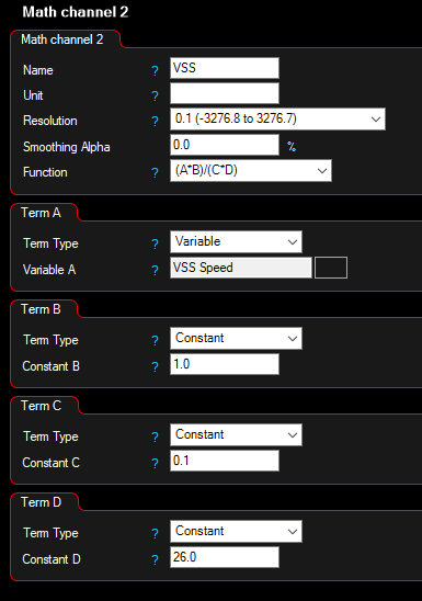
This could probably be simplified, but this worked for me and I had bigger fish to fry. Next up we can check out the two bit-builder channels, which are used to build out messages bit-by-bit (hurr):
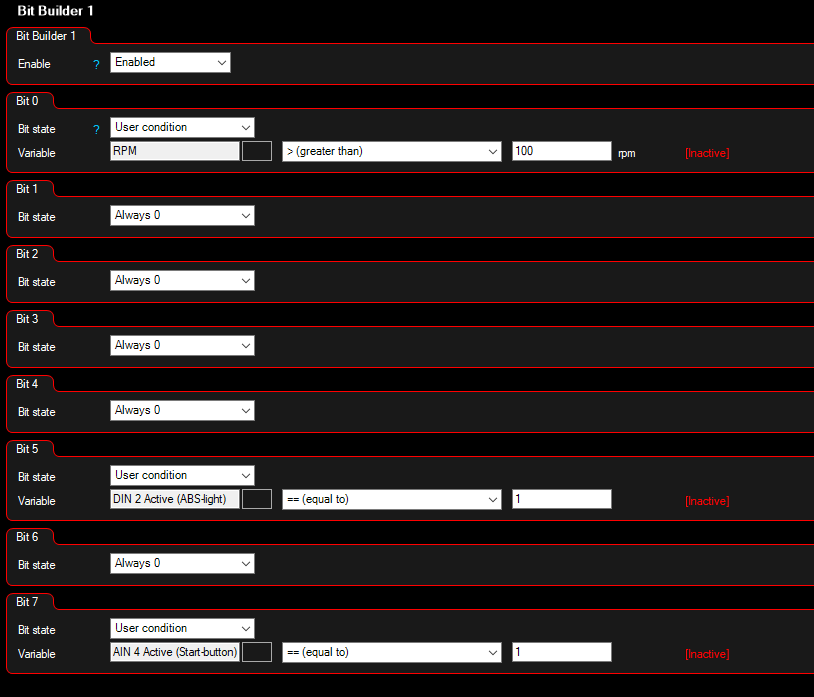
The above message sets the run, ABS light and start-button bits. The start-button bit is used to tell the dashboard that the engine is cranking and that it should shut off the headlight to help out the starter motor.
The second bit-builder channel sets up the shift light message:
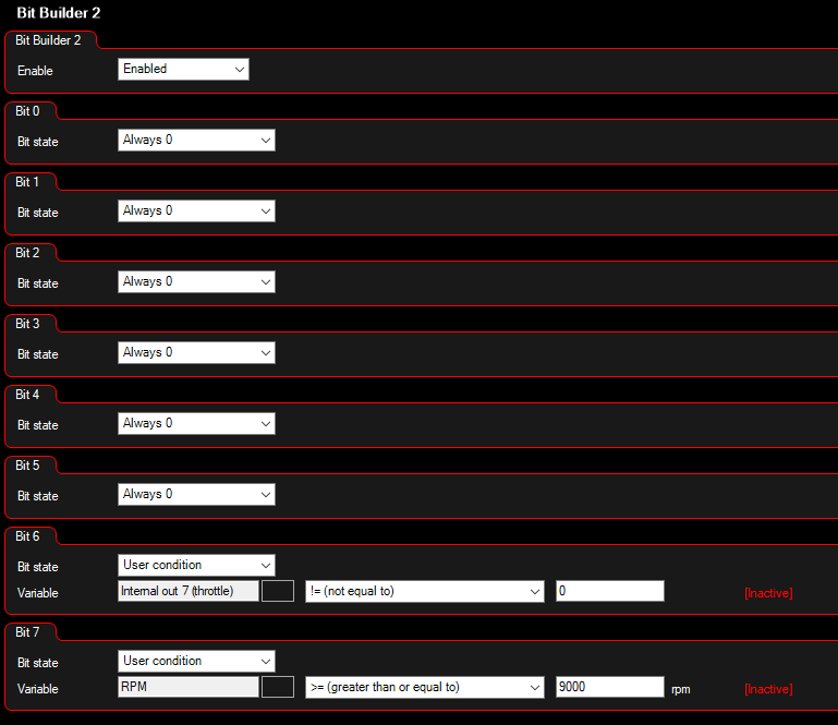
The internal-output on bit 6 I set up to an internal output that I could configure to blink at me when certain conditions were met, like when the throttle was between two values where I wanted to datalog. When the shift-light blinked at me, I knew I was in the area I wanted and could maintain that throttle position/rpm.
0x211
The next message contained temperature sensor data. From Part I, we know the message structure is:
     211#4E880037d4000000
         │ │ - │ │ - - -
         │ │   │ └─────Air pressure?
         │ └┐  │
Engine temp │  └─────┐
           Volts     │
                    Ambient temp
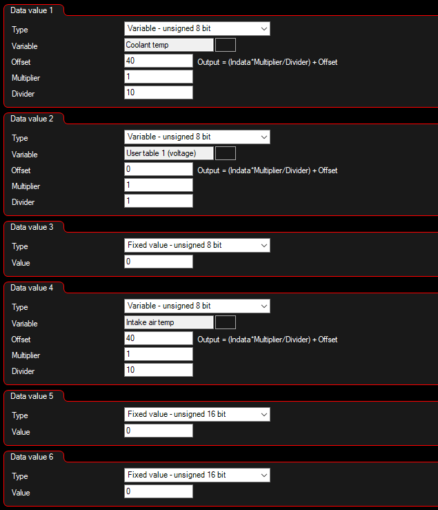
The voltage used an annoying format, so this needed an additional table to turn the actual voltage value in the data expected by the dashboard:

Inputs
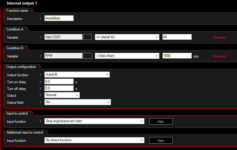
I’m not particularly interested in the data coming out of the dashboard right now, except for the immobilizer bit. By reading this bit, the immobilizer functionality can get re-implemented in the aftermarket ECU. This is implemented in the third byte of message 0x20 (similar to the Ducati 848 discussed here so if we read a 16-bit integer at byte offset 1, we get the immobilizer flag as 0x0040 (64) when it’s active.
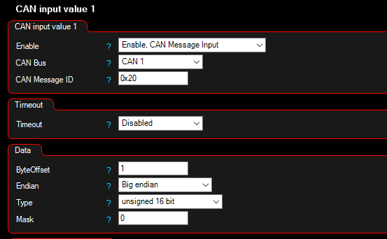
The stock Ducati system had a flaw where if the immobilizer bit was reset, the engine would be cut, even if its currently at 9000rpm exiting turn 2 at Hampton Downs. Since we now control the configuration, it’s easy to add in an additional safety check that only allows the immobilizer to cut the motor when it’s not already on.
CANBUS Summary
Configuring the inputs and outputs took some experimentation where vehicle speed and bit data was serialized into one 16-bit integer, but aside from that this setup was reasonably straight forward. The data on the dashboard matched what was read out in the ECU log.
The mission of using an aftermarket ECU with the stock Ducati dashboard was a success.
ECU Reversing - Starting Fuel Maps and Ignition Tables
As you can imagine, there aren’t a lot of Ducati’s with MaxxECU brains, so a base map to start tuning from is out of the question. This next part is effectively just a nerd-flex, and you can definitely build out ignition and fuel maps from scratch. Professional tuners have been doing precisely that since ECUs were first invented, so there is a lot of industry knowledge around that practice.
The aim here was to save some time building maps by spending time hardware hacking, and I can explain some of the interesting ECU reversing steps along the way. The goal is simple, dump the ECU flash and extract the factory ignition and fuel tables.
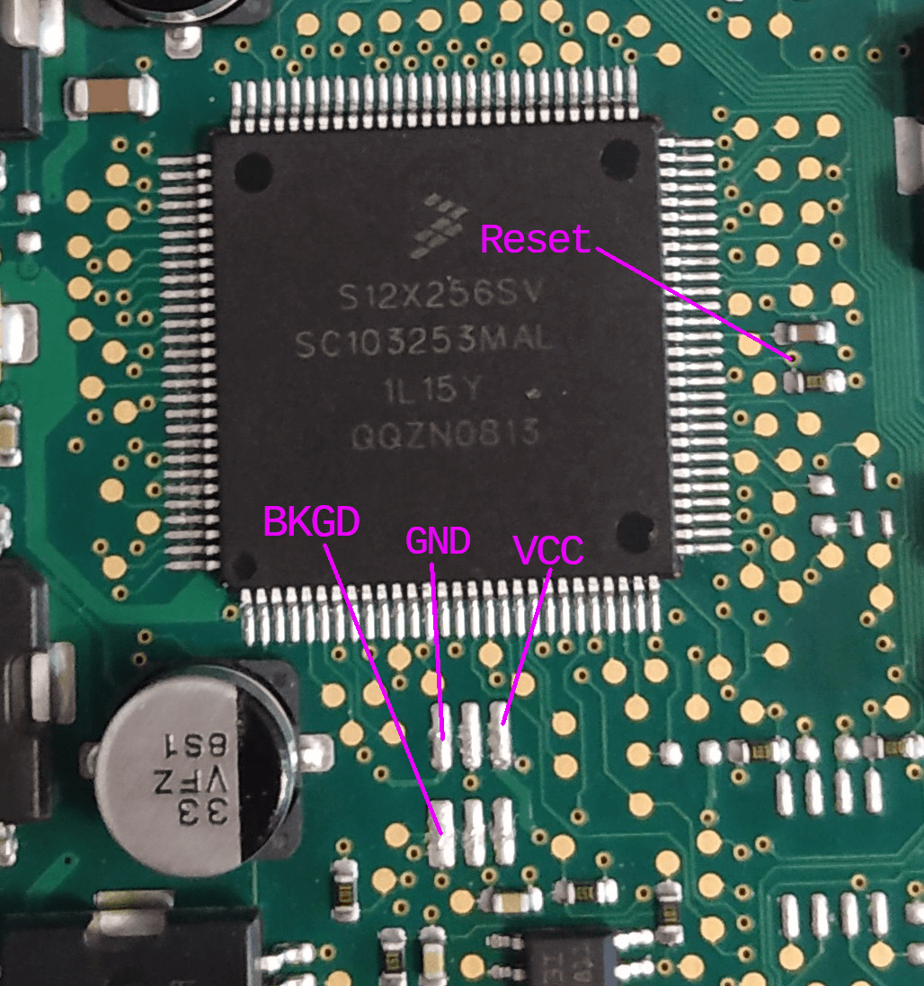
First off, I needed a test ECU. I found some spares from various wreckers and picked up a Monster 696 and Hypermotard 796 ECU to take apart. These next parts are all done on the bench. We need to identify the chip:
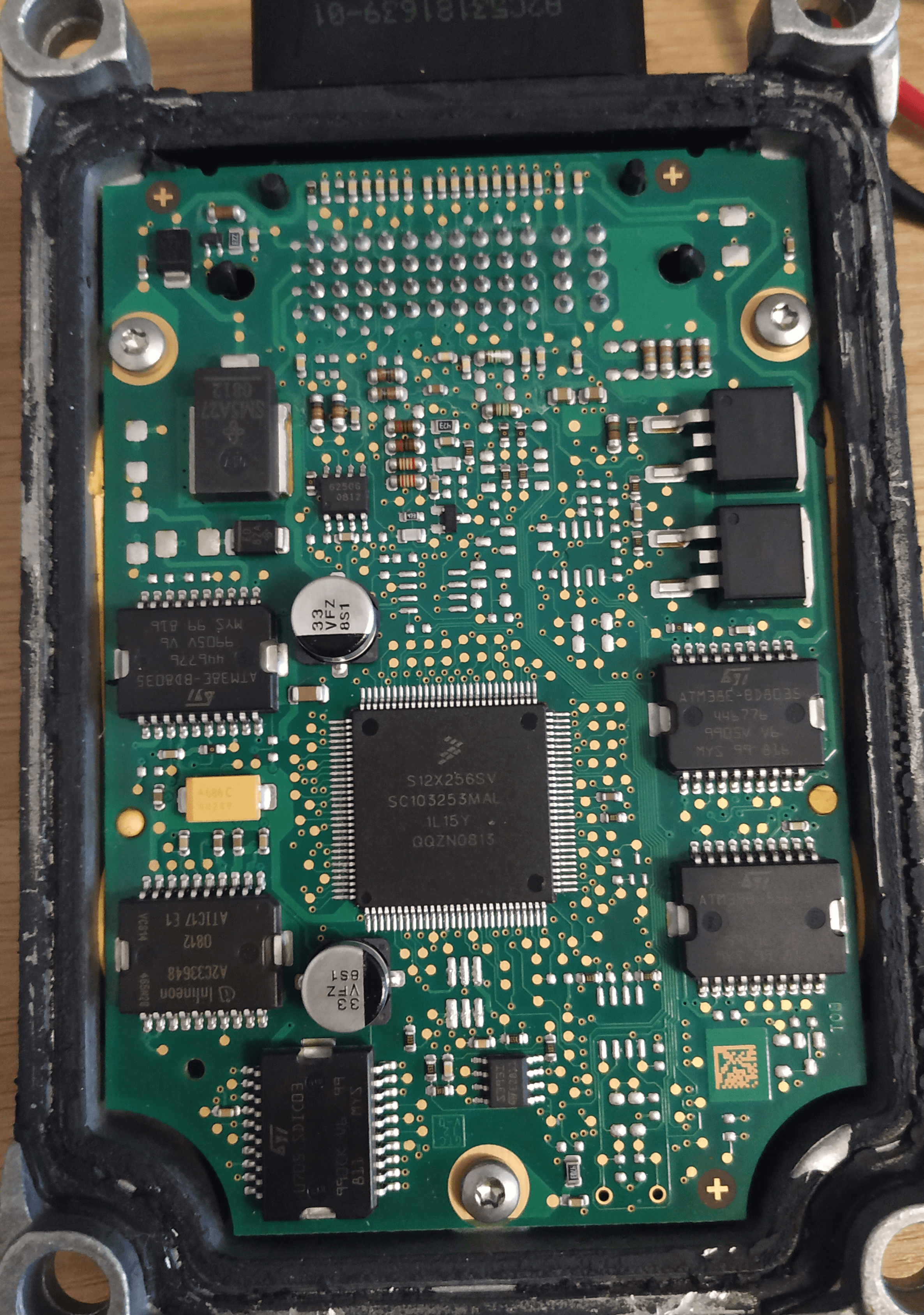
The chip code above is S12X256SV, which doesn’t immediately map to an available datasheet. The 796 Hypermotard ECU has a much more common chip, aside from that the board appears to be the same:
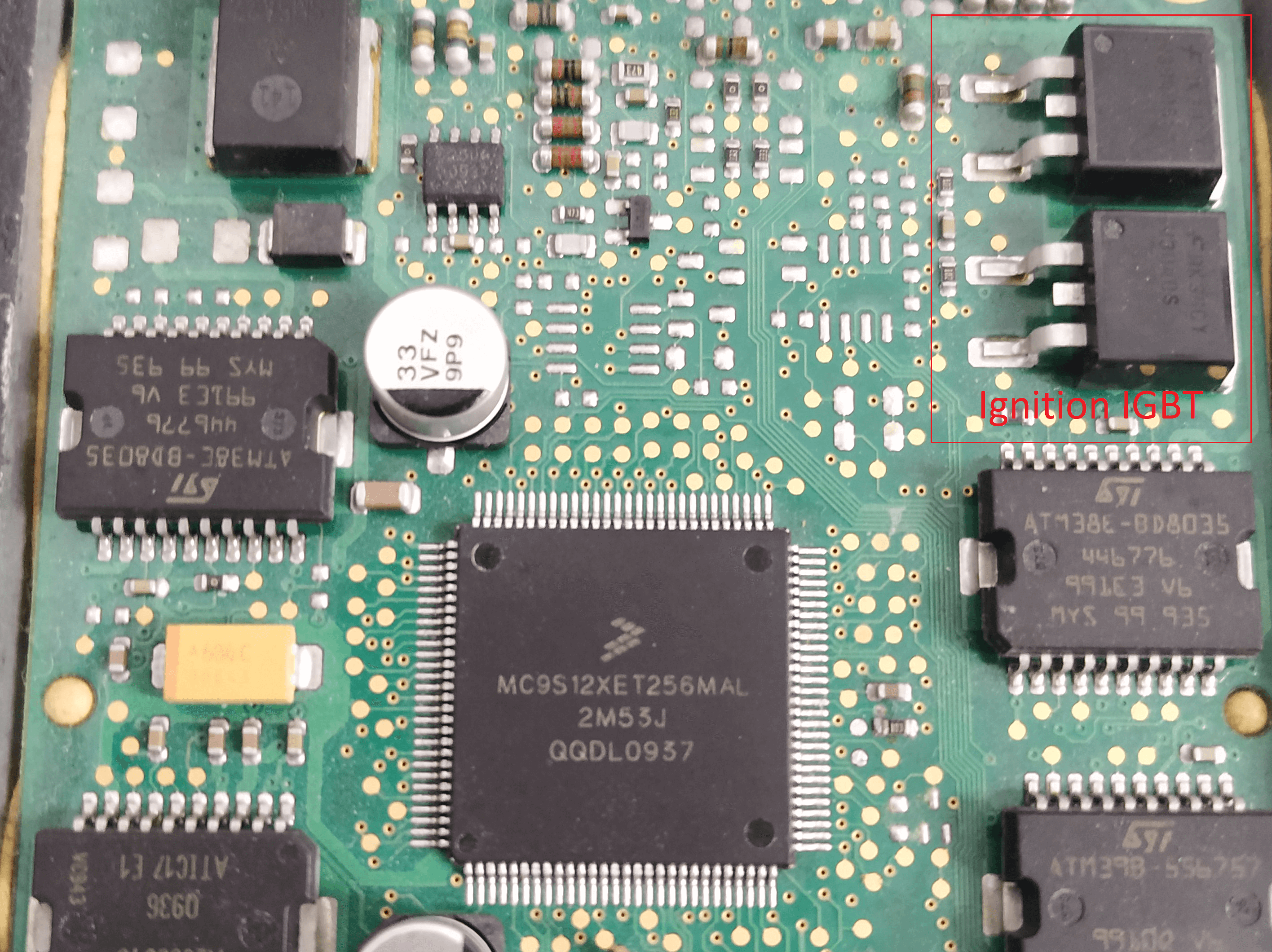
Those big ol’ IGBTs are what switch the ignition coils. I went to LS2 coils since the MaxxECU doesn’t have these igniter IGBTs built in and needs to use ‘smart coils’. I could have also used an external IGBT igniter, but I figured some more spark energy couldn’t hurt.
These are S12X chips, part of the 68HC12 family. You can find the data sheets online, and they include a lot of cool stuff, like an XGATE co-processor that runs at twice the clock speed on a different architecture but shares the memory space with the main core. Neat stuff.
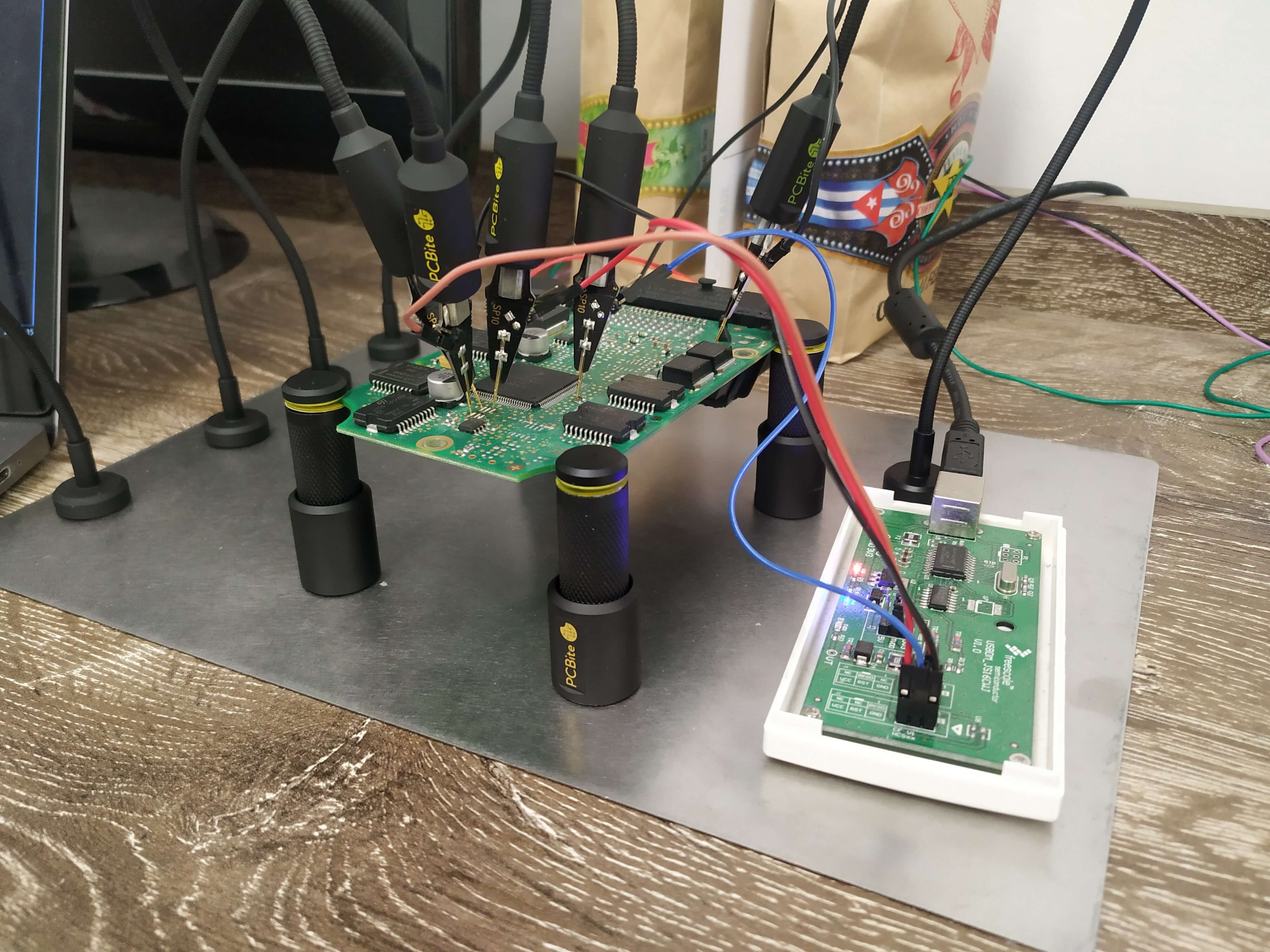
My goal is to extract the firmware, so to do that we need to identify the chip debug interface. The S12X chips in the above ECUs use the BDM (Background Debug Mode) interface, so I picked up a USBDM interface from AliExpress and probed the board. Details on the BDM pads were already available on various forums, so I didn’t need to do much reversing there:
Running a 12V power supply to the two +12V pins on the main connector, some poking with probes and we’re off:
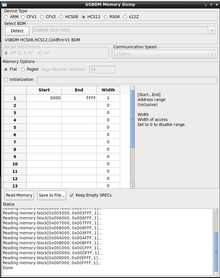
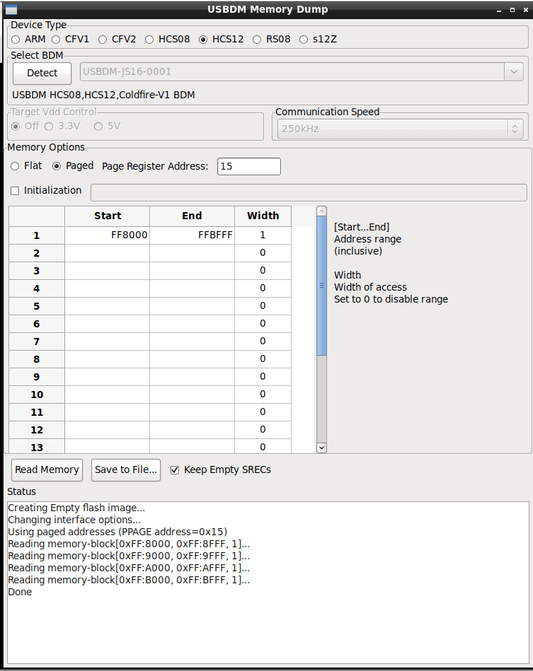
Using the USBDM tools https://usbdm.sourceforge.io/USBDM_V4.12/html/index.html, I can dump some memory from the logical memory space, in this case 0x0000 to 0xFFFF:
Hit “Save to file” and save the S19 file:
doi@krntija:~/article$ ls -rltha
total 180K
drwxr-xr-x 30 doi doi 4.0K Jun  3 17:23 ..
drwxr-xr-x  2 doi doi 4.0K Jun  3 17:24 .
-rw-r--r--  1 doi doi 172K Jun  3 17:24 logical-0000-ffff.s19
doi@krntija:~/article$ tail logical-0000-ffff.s19
S113FF60F274F274F274F274F274F274F274F2745D
S113FF70F274F274F274F274F274F274F274F2744D
S113FF80F274F274F274F274F274F274F274F2743D
S113FF90F274F274F274F274F274F274F274F2742D
S113FFA0F274F274F274F274F274F274F274F2741D
S113FFB0F274F274F274F274F274F274F274F2740D
S113FFC0F274F274F274F274F274F274F274F274FD
S113FFD0F274F274F274F274F274F274F274F274ED
S113FFE0F274F274F274F274F274F274F274F274DD
S113FFF0F274F274F274F274F275F279F27DF281B1
USBDM Memory dump spits out an S-record file. The first part (S113FFF0) is the header and memory address, then 16 bytes of data, then a checksum byte. You can read more about S-records on the Wikipedia page (https://en.wikipedia.org/wiki/SREC_(file_format)). We can use srec2bin (https://github.com/arkku/srec) to go from the s19 file to a binary file.
doi@krntija:~/article$ ~/src/srec/srec2bin -o logical-0000-ffff.bin -i logical-0000-ffff.s19
doi@krntija:~/article$ xxd logical-0000-ffff.bin | tail -25
0000fe70: ffff ffff ffff ffff ffff ffff ffff ffff  ................
0000fe80: ffff ffff ffff ffff ffff ffff ffff ffff  ................
0000fe90: ffff ffff ffff ffff ffff ffff ffff ffff  ................
0000fea0: ffff ffff ffff ffff ffff ffff ffff ffff  ................
0000feb0: ffff ffff ffff ffff ffff ffff ffff ffff  ................
0000fec0: ffff ffff ffff ffff ffff ffff ffff ffff  ................
0000fed0: ffff ffff ffff ffff ffff ffff ffff ffff  ................
0000fee0: ffff ffff ffff ffff ffff ffff ffff ffff  ................
0000fef0: ffff ffff ffff ffff ffff ffff ffff ffff  ................
0000ff00: ffff ffff ffff ffff ffff ffff ffff fffe  ................
0000ff10: f274 f274 f274 f274 f274 f274 f274 f274  .t.t.t.t.t.t.t.t
0000ff20: f274 f274 f274 f274 f274 f274 f274 f274  .t.t.t.t.t.t.t.t
0000ff30: f274 f274 f274 f274 f274 f274 f274 f274  .t.t.t.t.t.t.t.t
0000ff40: f274 f274 f274 f274 f274 f274 f274 f274  .t.t.t.t.t.t.t.t
0000ff50: f274 f274 f274 f274 f274 f274 f274 f274  .t.t.t.t.t.t.t.t
0000ff60: f274 f274 f274 f274 f274 f274 f274 f274  .t.t.t.t.t.t.t.t
0000ff70: f274 f274 f274 f274 f274 f274 f274 f274  .t.t.t.t.t.t.t.t
0000ff80: f274 f274 f274 f274 f274 f274 f274 f274  .t.t.t.t.t.t.t.t
0000ff90: f274 f274 f274 f274 f274 f274 f274 f274  .t.t.t.t.t.t.t.t
0000ffa0: f274 f274 f274 f274 f274 f274 f274 f274  .t.t.t.t.t.t.t.t
0000ffb0: f274 f274 f274 f274 f274 f274 f274 f274  .t.t.t.t.t.t.t.t
0000ffc0: f274 f274 f274 f274 f274 f274 f274 f274  .t.t.t.t.t.t.t.t
0000ffd0: f274 f274 f274 f274 f274 f274 f274 f274  .t.t.t.t.t.t.t.t
0000ffe0: f274 f274 f274 f274 f274 f274 f274 f274  .t.t.t.t.t.t.t.t
0000fff0: f274 f274 f274 f274 f275 f279 f27d f281  .t.t.t.t.u.y.}..
It works! The interrupt vectors are where we expect them. We can dig through the memory dump a bit more and see if there are any interesting things:
000032a0: 0000 0000 0000 0000 0000 0000 0800 2000  .............. .
000032b0: 0000 e000 0000 0020 0000 0801 4220 0000  ....... ....B ..
000032c0: 0a85 000a d200 0000 0801 1000 0000 0000  ................
000032d0: 0000 0000 0000 0801 1020 0000 0000 0000  ......... ......
000032e0: 0000 0000 0801 5000 0000 2020 4d4f 4e53  ......P...  MONS
000032f0: 5445 0801 5200 0000 5220 3639 3620 2020  TE..R...R 696
00003300: 0801 4020 0000 0101 0000 0000 0000 0801  ..@ ............
00003310: 0000 0000 0000 0000 0090 6000 0000 0000  ..........`.....
Looks pretty hopeful… Now, before proceeding we need to understand the memory structure of an S12X chip. It’s a 16-bit micro-controller, with a 16-bit logical address space. The chip also has a 23-bit global address space, and uses various registers to page in different chunks of flash memory. Here is a picture from an NXP datasheet that explains the memory layout:
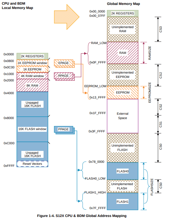
By changing the value of the PPAGE register, we can change the 16KB page which is currently between 0x8000 and 0xBFFF. The logical memory between 0xC000 and 0xFFFF is always mapped to the last PPAGE (0xFF), and 0x4000 to 0x7FFF is always PPAGE 0xFD, which is going to come in handy shortly. If you’d like to read more about S12X addressing specifics, I found this write up handy.
The PPAGE register correlates to the global flash space, from highest address to lowest. For example, PPAGE 0xFF pages in 0x7F_C000 to 0x7F_FFFF from the global memory into the logical address space between 0x8000 and 0xBFFF so the CPU can access that data. 0xFE pages in 0x7F_8000 to 0x7F_BFFF and so forth.
Most of the time, you can look up the chip data sheet based on what’s printed on the chip, find how the flash is laid out and the specific PPAGE values for your specific chip. This was the case with the Hypermotard 796 ECU, that data-sheet is easy to find, so I used this to make sure my tooling was working correctly.
The Monster 696 ECU chip is more challenging to find info on though, so lets figure it out for ourselves.
There are two questions that need answering:
- Where is the
PPAGEregister - What are the
PPAGEvalues for the flash memory
Figuring out the PPAGE registers
After reading way, way too many datasheets, I determined the PPAGE register is going to be either 0x0015 or 0x0030. If we look at the logical memory dump we took earlier, one of these locations will likely make sense, while the other will not:
00000000: 000e 0000 0000 0000 9100 0100 d000 3f07  ..............?.
00000010: 0000 0000 0000 fdfe 0000 c411 4000 4000  ............@.@.
00000020: 0000 0000 0000 0000 0000 0000 0000 0000  ................
00000030: fe00 4000 0000 001c 0000 f100 0000 8000  ..@.............
00000040: 0000 0000 0000 0000 0000 0000 0000 0000  ................
A PPAGE register set to 0x00 doesn’t make much sense, but a PPAGE register set to 0xFE does. So, hint number one that this chip uses a PPAGE register at 0x0030.
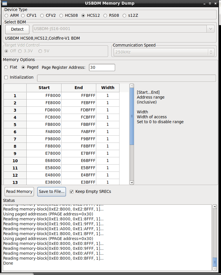
An easy way to check this is to cross-reference the non-paged memory sections. Remember how the logical memory between 0xC000 and 0xFFFF is always mapped to the last page (0xFF), and 0x4000 to 0x7FFF is always page 0xFD? We can check if we’ve found the right PPAGE register by setting either 0x0015 or 0x0030 to 0xFF, and seeing if the data in the page window (0x8000-0xBFFF) matches what’s between 0xC000 and 0xFFFF.
We already have a complete logical memory dump, so lets try pull out page 0xFF using 0x0015 register as the PPAGE. I expect this to fail. The first byte in the stand and end addresses is the value that will be written to the PPAGE register specified in the Page Register Address field.
Then we check out the data. We need to do some DD trickery, since the resulting s19 file from the memory dumper will put our data at offset 0xFF_8000 in the resulting binary file:
doi@krntija:~/article$ ~/src/srec/srec2bin -o ppage15-ff.bin -i ppage15-ff.s19
doi@krntija:~/article$ ls -lrtha
total 308K
drwxr-xr-x 30 doi doi 4.0K Jun  3 17:23 ..
-rw-r--r--  1 doi doi 172K Jun  3 17:24 logical-0000-ffff.s19
-rw-r--r--  1 doi doi  64K Jun  3 17:27 logical-0000-ffff.bin
-rw-r--r--  1 doi doi  45K Jun  3 17:43 ppage15-ff.s19
drwxr-xr-x  2 doi doi 4.0K Jun  3 17:43 .
-rw-r--r--  1 doi doi  16M Jun  3 17:46 ppage15-ff.bin
doi@krntija:~/article$ dd if=ppage15-ff.bin skip=$((0xFF8000)) bs=1 count=$((0x4000)) | xxd | tail
00003f60: ffff ffff ffff ffff ffff ffff ffff ffff  ................
00003f70: ffff ffff ffff ffff ffff ffff ffff ffff  ................
00003f80: ffff ffff ffff ffff ffff ffff ffff ffff  ................
00003f90: ffff ffff ffff ffff ffff ffff ffff ffff  ................
00003fa0: ffff ffff ffff ffff ffff ffff ffff ffff  ................
00003fb0: ffff ffff ffff ffff ffff ffff ffff ffff  ................
00003fc0: ffff ffff ffff ffff ffff ffff ffff ffff  ................
00003fd0: ffff ffff ffff ffff ffff ffff ffff ffff  ................
00003fe0: ffff ffff ffff ffff ffff ffff ffff ffff  ................
00003ff0: ffff ffff ffff ffff ffff ffff ffff ffff  ................
16384+0 records in
16384+0 records out
16384 bytes (16 kB, 16 KiB) copied, 0.0666392 s, 246 kB/s
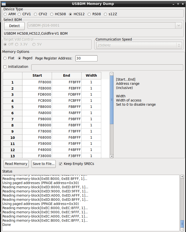
That doesn’t look right, it’s all 0xFF bytes. Lets repeat the process with 0x0030, which I expect to match:
doi@krntija:~/article$ dd if=ppage30-ff.bin skip=$((0xFF8000)) bs=1 count=$((0x4000)) | xxd | tail
16384+0 records in
16384+0 records out
16384 bytes (16 kB, 16 KiB) copied, 0.0293645 s, 558 kB/s
00003f60: f274 f274 f274 f274 f274 f274 f274 f274  .t.t.t.t.t.t.t.t
00003f70: f274 f274 f274 f274 f274 f274 f274 f274  .t.t.t.t.t.t.t.t
00003f80: f274 f274 f274 f274 f274 f274 f274 f274  .t.t.t.t.t.t.t.t
00003f90: f274 f274 f274 f274 f274 f274 f274 f274  .t.t.t.t.t.t.t.t
00003fa0: f274 f274 f274 f274 f274 f274 f274 f274  .t.t.t.t.t.t.t.t
00003fb0: f274 f274 f274 f274 f274 f274 f274 f274  .t.t.t.t.t.t.t.t
00003fc0: f274 f274 f274 f274 f274 f274 f274 f274  .t.t.t.t.t.t.t.t
00003fd0: f274 f274 f274 f274 f274 f274 f274 f274  .t.t.t.t.t.t.t.t
00003fe0: f274 f274 f274 f274 f274 f274 f274 f274  .t.t.t.t.t.t.t.t
00003ff0: f274 f274 f274 f274 f275 f279 f27d f281  .t.t.t.t.u.y.}..
Much better. Lets confirm this matches what’s between 0xC000 and 0xFFFF in the logical memory dump:
doi@krntija:~/article$ dd if=ppage30-ff.bin skip=$((0xFF8000)) bs=1 count=$((0x4000)) > pageFF.bin
16384+0 records in
16384+0 records out
16384 bytes (16 kB, 16 KiB) copied, 0.0433657 s, 378 kB/s
doi@krntija:~/article$ dd if=logical-0000-ffff.bin bs=1 count=$((0x4000)) skip=$((0xC000)) > logicalFF.bin
16384+0 records in
16384+0 records out
16384 bytes (16 kB, 16 KiB) copied, 0.0497264 s, 329 kB/s
doi@krntija:~/article$ md5sum logicalFF.bin
8bd3dad69a1af0b0bfebd7d9ec1aca43  logicalFF.bin
doi@krntija:~/article$ md5sum pageFF.bin
8bd3dad69a1af0b0bfebd7d9ec1aca43  pageFF.bin
Awesome. The data matches, our PPAGE register is 0x0030.
Dumping the Flash Pages
In some S12X chips, the flash is split up into FLASH0 and FLASH1, with a chunk of unimplemented flash between them (as shown in the memory layout figure earlier in this article). The datasheet explains where FLASH0_LOW and FLASH1_HIGH are set for each specific chip, or if there is no splitting at all.
So… How do we figure this out?
Being Smart
The first way I tried to figure out the memory block layout was to be smart. This didn’t work. If you want to fast-forward to what did work, skip ahead to “being dumb”.
There are two other registers which we can see in the logical memory dump, PARTIDH and PARTIDL at addresses 0x001A and 0x001B. We can use these to google around and find more information, even when what’s on the chip silk doesn’t give us the info straight away. In this case, our part ID is 0xC411:
00000000: 000e 0000 0000 0000 9100 0100 d000 3f07  ..............?.
00000010: 0000 0000 0000 fdfe 0000 c411 4000 4000  ............@.@.
We can google that and get another data sheet to read through:

And hey hey, memory layout table.

Now that we have an idea of the memory layout, we can build a list of PPAGE values that we want to extract.
| Flash Block | Global Memory Range | PPAGE Values |
|---|---|---|
FLASH0 |
0x78_0000 to 0x79_FFFF |
E0,E1,E2,E3,E4,E5,E6,E7 |
FLASH1 |
0x7E_0000 to 0x7F_FFFF |
F8,F9,FA,FB,FC,FD,FE,FF |
We can check out the S19 file directly and see the block data. Empty pages will be set to all 0xFF:
doi@krntija:~/article/flashdump$ cat flashdump.s19
S214E08000FFFFFFFFFFFFFFFFFFFFFFFFFFFFFFFF9B
S214E08010FFFFFFFFFFFFFFFFFFFFFFFFFFFFFFFF8B
S214E08020FFFFFFFFFFFFFFFFFFFFFFFFFFFFFFFF7B
S214E08030FFFFFFFFFFFFFFFFFFFFFFFFFFFFFFFF6B
S214E08040FFFFFFFFFFFFFFFFFFFFFFFFFFFFFFFF5B
S214E08050FFFFFFFFFFFFFFFFFFFFFFFFFFFFFFFF4B
S214E08060FFFFFFFFFFFFFFFFFFFFFFFFFFFFFFFF3B
S214E08070FFFFFFFFFFFFFFFFFFFFFFFFFFFFFFFF2B
S214E08080FFFFFFFFFFFFFFFFFFFFFFFFFFFFFFFF1B
S214E08090FFFFFFFFFFFFFFFFFFFFFFFFFFFFFFFF0B
...omg so many 0xFF...
S214F88400C400F000C400F000C400F000C400F0009F
...yoink...
doi@krntija:~/article/flashdump$ strings flashdump.bin | grep -i monst
doi@krntija:~/article/flashdump$
We don’t get anything until page 0xF8 (the beginning of Flash1). We’re missing Flash0. Also, if we strings the binary we don’t see the start-up text that we saw in the RAM area. We’re missing flash information. Looks like the data sheet was for a different chip. Dangit.
Being Dumb
Okay so since being clever didn’t work, let’s be dumb. Instead of worrying about the chip being a 256K chip with potentials splits and offsets and all that nonsense, we’ll just dump every possible PPAGE referencing flash memory between 0x78_0000 and 0x7F_0000. So that’ll be every PPAGE from E0 to FF.
I figure, worst case scenario we get more null pages to prune out. If setting an invalid PPAGE register would make the chip explode, then the chip was destined to explode. Que sera, sera.
If we don’t have the memory layout info, we can pretty easily dump every available flash page. If it’s invalid, we should get 16KB of 0xFF. We’ll need to run this twice, since the memory dumper utility supports 20 lines and we need to pull out 32 separate pages.
We end up with two s19 files.
doi@krntija:~/article/flashdumpyolo$ ls -lh
total 1.5M
-rw-r--r-- 1 doi doi 540K Jun  3 18:52 flashdumpeb-e0.s19
-rw-r--r-- 1 doi doi 900K Jun  3 18:41 flashdumpff-ec.s19
Pages E0 to EB were all set to 0xFF, so no dice there:
doi@krntija:~/article/flashdumpyolo$ head flashdumpeb-e0.s19
S214E08000FFFFFFFFFFFFFFFFFFFFFFFFFFFFFFFF9B
S214E08010FFFFFFFFFFFFFFFFFFFFFFFFFFFFFFFF8B
S214E08020FFFFFFFFFFFFFFFFFFFFFFFFFFFFFFFF7B
S214E08030FFFFFFFFFFFFFFFFFFFFFFFFFFFFFFFF6B
S214E08040FFFFFFFFFFFFFFFFFFFFFFFFFFFFFFFF5B
S214E08050FFFFFFFFFFFFFFFFFFFFFFFFFFFFFFFF4B
S214E08060FFFFFFFFFFFFFFFFFFFFFFFFFFFFFFFF3B
S214E08070FFFFFFFFFFFFFFFFFFFFFFFFFFFFFFFF2B
S214E08080FFFFFFFFFFFFFFFFFFFFFFFFFFFFFFFF1B
S214E08090FFFFFFFFFFFFFFFFFFFFFFFFFFFFFFFF0B
doi@krntija:~/article/flashdumpyolo$ perl -pe 's/^\w{10}//; s/\w\w$//;' < flashdumpeb-e0.s19  | sort | uniq -c
  12288 FFFFFFFFFFFFFFFFFFFFFFFFFFFFFFFF
doi@krntija:~/article/flashdumpyolo$
If we grep out the FF only chunks, our first page with data is F0:
doi@krntija:~/article/flashdumpyolo$ grep -v 'FFFFFFFFFFFFFFFFFFFFFFFFFFFFFFFF' flashdumpff-ec.s19 | head
S214F08000FFFFFFFFCD54000D00FD800000FDB427FC
S214F0801000FDBE0000FDBE1900FDBF1000FDBFFF55
S214F0802000FF940000FFA17200F081C000F0BFF7DF
S214F0803000FC800000FC991800F1800000F1A7FF1A
S214F0804000F3800000F3BFFF00F4800000F4BFFFF1
S214F0805000F5800000F5BFFF00F6800000F6BFFFD9
S214F0806000F7800000F7BFFF00F8840000F8BFFEBE
S214F0815000FFFFFF51443038323031305144303870
S214F081603230FFFF31303133393231374141202060
S214F081705858585831313151443035303832303023
So what does that mean? Our first PPAGE starts at F0, our last PPAGE is at FF. That’s 16 pages of 16KB, our full 256KB stamped on the chip. We’ve successfully dumped all the flash memory. As a quick test, we can convert to binary and check if our missing string is there:
doi@krntija:~/article/flashdumpyolo$ ~/src/srec/srec2bin -o flashdumpff-ec.bin -i flashdumpff-ec.s19
doi@krntija:~/article/flashdumpyolo$ strings flashdumpff-ec.bin |grep -i monst
  696   MONSTER
There you go. When being smart doesn’t work, try being dumb.
Let’s always be stupid. Forever! - Finn the Human
Reassembling the Flash Image
The next hurdle is cutting down the S19 image into a 256K binary blob so we can dig through it and look for map data. When simply running srec2bin, the resulting binary file has data at the incorrect offsets. This is due to how the memory dump tool is using the first part of the address as the PPAGE register. 0xF0_8000, for example, isn’t a valid global memory address.
If you were looking at reverse-engineering and disassembling the firmware then you’d reassemble the extracted flash pages to match the global addressing scheme, with PPAGE FF at 0x7F_C000, PPAGE FE at 0x7F_8000, and so forth. Since all of our memory pages are next to each other, we can start by pulling each of the pages out into a 256KB binary blob:
doi@krntija:~/article/flashdumpyolo$ i=$((0xF08000)); while [ $i -le $((0xFF8000)) ] ; do dd if=flashdumpff-ec.bin bs=1 count=$((0x4000)) skip=$i; i=$(($i+0x10000)); done > flashdump.bin
16384+0 records in
16384+0 records out
16384 bytes (16 kB, 16 KiB) copied, 0.0622458 s, 263 kB/s
...yoink...
doi@krntija:~/article/flashdumpyolo$ ls -lrtha
total 2.0M
-rw-r--r-- 1 doi doi 900K Jun  3 18:41 flashdumpff-ec.s19
-rw-r--r-- 1 doi doi 540K Jun  3 18:52 flashdumpeb-e0.s19
drwxr-xr-x 6 doi doi 4.0K Jun  3 23:07 ..
-rw-r--r-- 1 doi doi  16M Jun  3 23:34 flashdumpff-ec.bin
drwxr-xr-x 2 doi doi 4.0K Jun  3 23:39 .
-rw-r--r-- 1 doi doi 256K Jun  3 23:39 flashdump.bin
doi@krntija:~/article/flashdumpyolo$ xxd flashdump.bin |tail
0003ff60: f274 f274 f274 f274 f274 f274 f274 f274  .t.t.t.t.t.t.t.t
0003ff70: f274 f274 f274 f274 f274 f274 f274 f274  .t.t.t.t.t.t.t.t
0003ff80: f274 f274 f274 f274 f274 f274 f274 f274  .t.t.t.t.t.t.t.t
0003ff90: f274 f274 f274 f274 f274 f274 f274 f274  .t.t.t.t.t.t.t.t
0003ffa0: f274 f274 f274 f274 f274 f274 f274 f274  .t.t.t.t.t.t.t.t
0003ffb0: f274 f274 f274 f274 f274 f274 f274 f274  .t.t.t.t.t.t.t.t
0003ffc0: f274 f274 f274 f274 f274 f274 f274 f274  .t.t.t.t.t.t.t.t
0003ffd0: f274 f274 f274 f274 f274 f274 f274 f274  .t.t.t.t.t.t.t.t
0003ffe0: f274 f274 f274 f274 f274 f274 f274 f274  .t.t.t.t.t.t.t.t
0003fff0: f274 f274 f274 f274 f275 f279 f27d f281  .t.t.t.t.u.y.}..
What the loop is doing here is extracting 16K bytes starting with the first PPAGE (0xF0) which is stored at offset 0xF0_8000 in the srec2bin-ed binary file, then moving onto the next 16K page at 0xF18000 and so forth. Our first memory page in the global memory map should be at 0x7C_0000.
What we can do now is re-assemble this with the logical memory dump we took at the beginning and feed that all into Ghidra. Again, the aim is to re-assemble a valid global memory map. The commands below create a binary blob of the logical memory space (0x0000 to 0xFFFF), pad the file with null bytes until the start of the flash memory, then add in our re-assembled 256KB flash blob from earlier.
doi@krntija:~/article/disassembly$ ~/src/srec/srec2bin -o 696-global-memory.bin -i ../logical-0000-ffff.s19
doi@krntija:~/article/disassembly$ dd if=/dev/zero of=696-global-memory.bin bs=1 seek=$((0x10000)) count=$((0x7C0000-0x10000))
8060928+0 records in
8060928+0 records out
8060928 bytes (8.1 MB, 7.7 MiB) copied, 12.762 s, 632 kB/s
doi@krntija:~/article/disassembly$ cat ../flashdumpyolo/flashdump.bin  >> 696-global-memory.bin
The result is something we can load into Ghidra using the HCS12 disassembler and start reversing. Loading this file into Ghidra finds a bunch of functions, and lets you work from the interrupt vectors downwards.
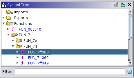
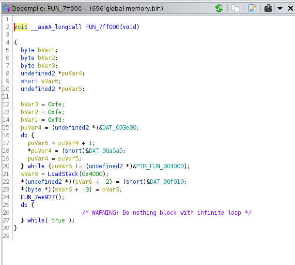
Between this, and live debugging though Codewarrior (the NXP IDE) and the USBDM interface, this is a good position to start understanding the ECU and doing some smarter reverse engineering. There is also a second processor in here, the XGATE co-processor, with its own RAM and instruction set, which raises the question of what functionality is handled by the core CPU, and what’s handled by the XGATE? Ghidra will happily decompile what’s in the S12X part of the firmware, but the XGATE co-processor not so much.
Interesting to think about; however, remembering that our goal here is to pull out the fuel and ignition tables, let’s move on.
Map Hunting with GNUPlot
The aim of the game is to find starting fuel map and ignition table data in the factory ECU, and transplant that into the aftermarket ECU as a starting point for tuning. A wiser person would probably look at one of the many publicly available BIN files for the Monster 695 (the previous generation with the same engine but a different, already heavily reverse engineered ECU) which have Tuner Pro definition files already available and yank the starting maps out of that instead.
Before getting stuck into rummaging around the flash file and hunting for maps, its a good idea to think about overall system architecture. What I mean by this is: The more you understand of a system, the easier reverse engineering will be. For example, If you’re looking for spark-advance tables in a common-rail diesel ECU, you’re going to have a bad time (for the non-automotive-savvy reading this, diesel engines don’t have spark plugs). Figuring out what sensors are on the engine can point to what strategy is in use. Looking up some publicly available automotive firmware or configurations for similar engine setups can also help you better understand how engine management for your platform could potentially work.
This whole thinking-about-the-architecture schtick can be a double-edged sword, and if you go into a system with too many assumptions, it can be easy to miss things that are right in front of you because they don’t follow some pattern you’ve thought up. I guess the trick is to use your intuition, but try not to get too caught up on how a system should work before you find the evidence that it does, indeed, work that way.
The ignition map will likely be degrees of ignition advance before top-dead-center, which should be straight forward. The fuel map could be using any number of algorithms to determine how long to pulse the injectors for. I don’t expect to be able to copy-paste out a fuel map and get perfect running with a completely different ECU, likely using a different algorithm. The goal here is to get the map information to have a starting point and general shape of the fuel map, then to continue tuning from there.
Anyway… we’re looking for three bits of data:
- Ignition map
- Fuel Map
- TPS and RPM break points
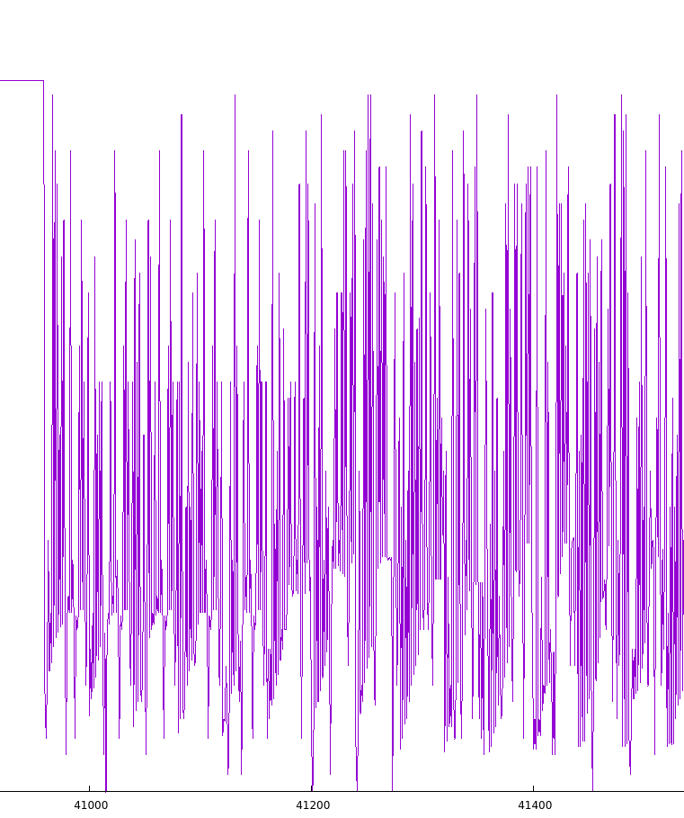
There are commercial automotive software products designed to help you hunt down these data structures in memory, but I’d like to demonstrate how you can visually locate maps and other structured data using GNUPlot. We’ll be plotting the flash data and searching for patterns which correlate with fuel or ignition map data. The idea is that code sections will generally be reasonably high in entropy, while data structures and configuration less so. Dropping the firmware into https://binvis.io shows the code sections with a wide range of bytes from 0x00 to 0xFF without any immediately determinable pattern:

Fuel and Ignition Maps
There are two main GNUPlot techniques I want to discuss – 2D line-graph searching and 3D visualisation. The idea is fairly straight forward, the maps and structured data will be visually different when compared to program code sections of the firmware.
Fire up GNUPlot, set the xrange to specify how much data to display, then plot the binary:
$ gnuplot

	G N U P L O T
	Version 5.2 patchlevel 6    last modified 2019-01-01

	Copyright (C) 1986-1993, 1998, 2004, 2007-2018
	Thomas Williams, Colin Kelley and many others

	gnuplot home:     http://www.gnuplot.info
	faq, bugs, etc:   type "help FAQ"
	immediate help:   type "help"  (plot window: hit 'h')

Terminal type is now 'qt'
gnuplot> set xrange [0:512]
gnuplot> plot 'flashdump.bin' binary format="%uint8" using 1 with lines
This is what pops up, and you can use the arrow keys or mouse wheel to scroll back and forth throughout the graph.
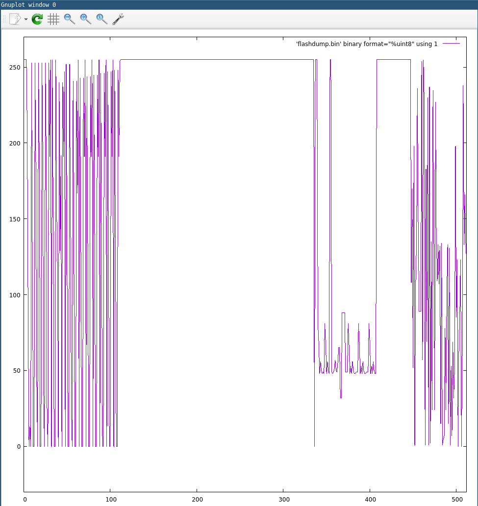
As we scroll along, we find a set of structured data, and something that looks a lot like a map:
This is the ignition table; we’ll dig into that a bit more soon.
We’re looking at 8 bit unsigned integers in the graph above, since we specified format=”%uint8” in the plot command. With a tweak to the plot command, we can look at 16-bit unsigned integers instead. This might make some map information make more sense.
Here’s a different chunk of data visualised as 8bit and 16bit:
We can view this as 16-bit big endian unsigned integers instead with:
gnuplot> plot 'flashdump.bin' binary format="%uint16" endian=big using 1 with lines
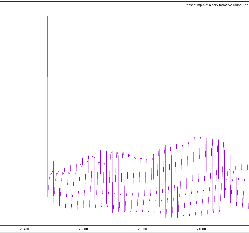
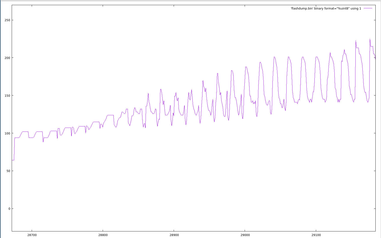
When plotted using 16-bit values, the data makes more sense, so it’s important to look at things as different types. In the 2D view, there is also some other information we can glean from the pattern above. By counting the number of peaks before the pattern resets, we can determine one of the dimensions of the map. In this case, there are 30 peaks, so the map will be n*30.
To determine the other dimension, I look at the values in a hex editor and count how many values before there is a sharp drop which denotes the next row. This works well for fuel and ignition tables, since as RPM increases an engine generally needs more fuel and more ignition advance. For other values, such as exhaust gas lambda targets that decrease as RPM increases, you’d apply the opposite.
0000A000   23 13 28 5A  2B 40 2E FA  34 E6 37 DA  39 80 3B C0  #.([email protected].;.
0000A010   3C CD 3E 0D  3F 46 40 E6  40 53 3F 13  3F 3A 3F A0  <.>.?F@.@S?.?:?.
0000A020   41 CD 41 93  4B 26 4E B3  1B 33 21 40  25 C0 29 80  A.A.K&N..3!@%.).
Looking at the above data (offset 0xA000) in a hex editor, we can determine that there are 20 16-bit integers before the value drops. The data goes 0x2313, 0x285A and so forth up to 0x4EB3, then the next value is 0x1B33. This indicates we have a 20x30 map of 16-bit unsigned integers at offset 0xA000.
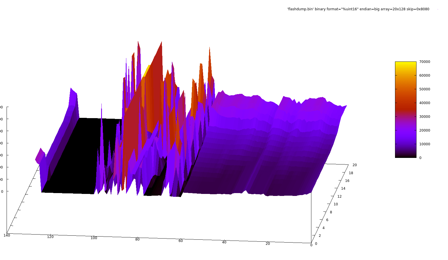
Lets use GNUPlot now to graph this as a 3D map and eyeball what’s going on. We’ll use the splot command for this:
gnuplot> set pm3d
gnuplot> splot 'flashdump.bin' binary format="%uint16" endian=big  array=20x30 skip=0xA000 pt
0.8
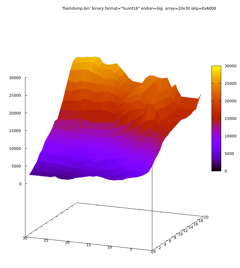
Setting set xrange [:] reverse makes it follow the zero-on-the-left display you’d expect from a fuel map:
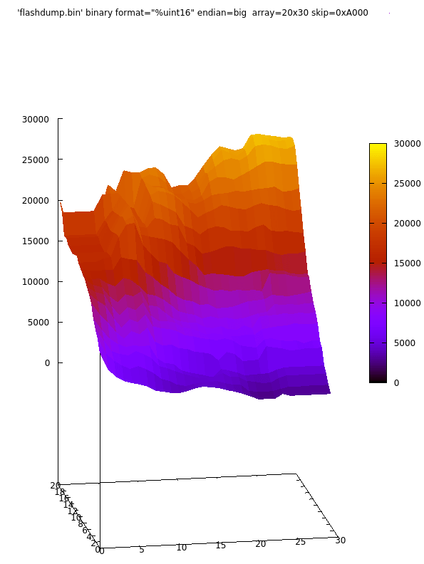
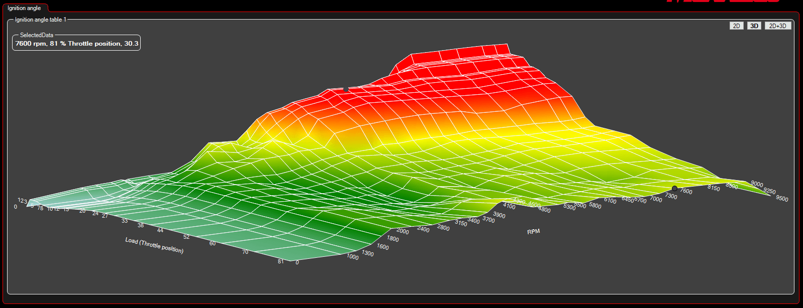
This looks like a good candidate for our fuel map! That’s one part of the question done. Let’s use the same technique with the 8 bit map we found originally:
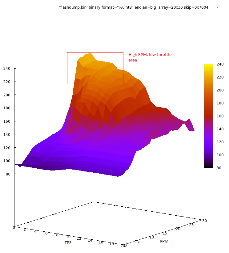
This looks like our ignition table. It’s following the general pattern of adding ignition advance as the RPM increases, with significant advance at high RPM at low throttle openings, and less so at high RPM wide open throttle when the engine will be under load and more susceptible to detonation. Finding the divisor for the values to turn them into ‘degrees of ignition advance’ are easiest with a timing light on a running engine. In this case, diving the map cell value by 5 gave the ignition advance in degrees before top-dead-center.
That’s two of our three targets down!
Before moving onto the break points, the 3D map visualization used above can also be used with the wider binary, similar to what was demonstrated with the 2D plotting. Take a look:
gnuplot> set yrange[0:512]
gnuplot> set pm3d
gnuplot> splot 'flashdump.bin' binary format="%uint16" endian=big array=16x16384 pt 0.8
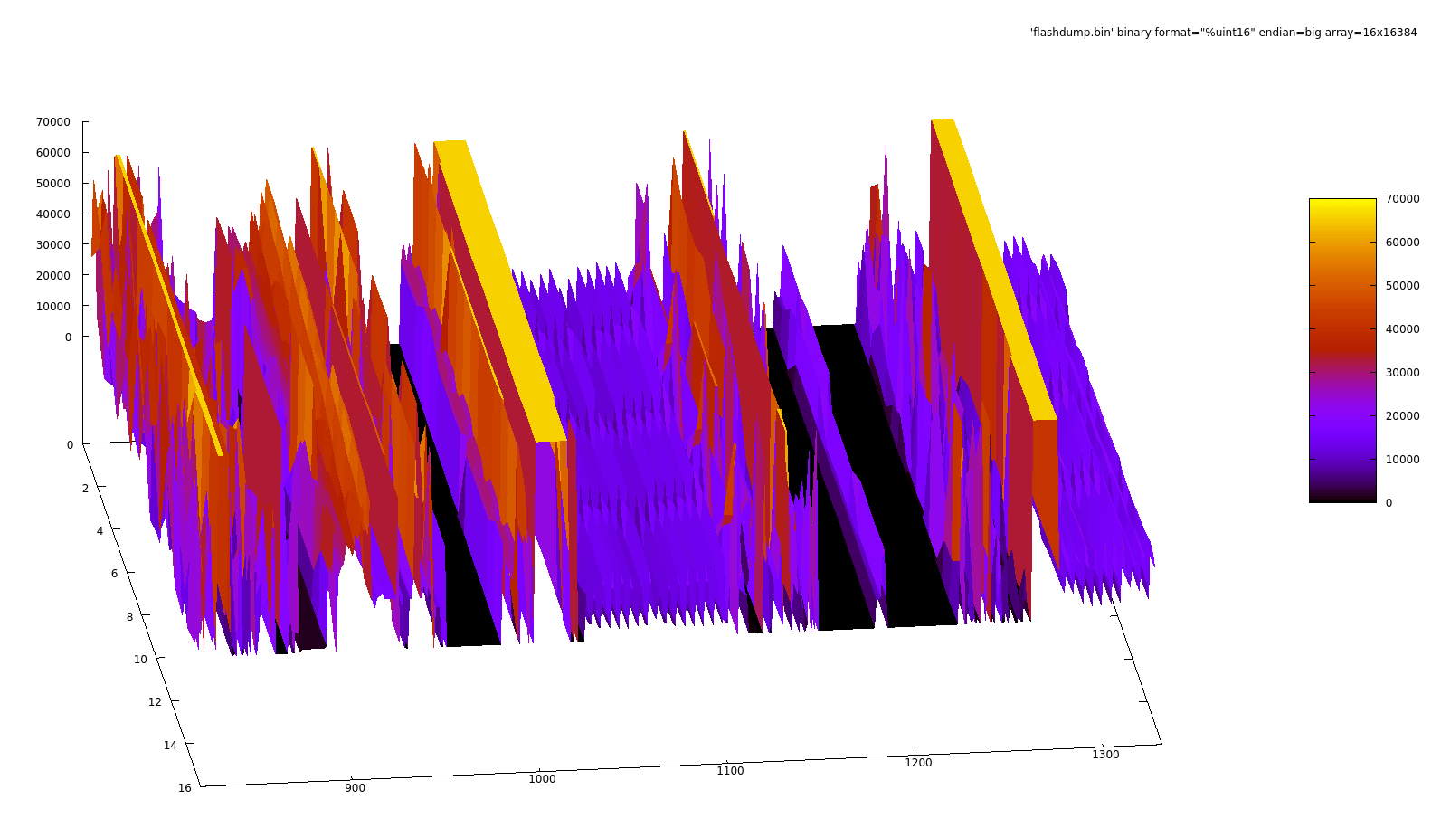
You can find valleys of data like the above by scrolling back and forth through the bin file, then alter the array dimensions and skip parameters to analyse different areas more closely:
Here we see two interesting maps side-by-side. If the aim of the game was to reflash the factory ECU, this is where I’d make an inventory of the possible maps and then check out the code disassembly to figure out how they’re used. We may find that the ECU uses multiple maps with different load axis (throttle position or manifold pressure, for example) depending on the running condition. Since we’re just looking for some starting data for the new ECU, and this doesn’t need to be particularly precise for the fuel table as tuning needs to happen anyway, I’m not going to go over this here.
TPS/RPM Break Points
The last bit of information we need before we can load all of this into the aftermarket ECU is the throttle position and RPM break points. These are the values associated with our 20 rows and 30 columns. What throttle position is ‘row 3’? That’s the question we’re trying to answer.
You’d think this would be an even divide between 0% throttle at row 0, and 100% at row 19, but this isn’t the case. The change to the amount of airflow on engines with individual throttle bodies is more significant at low throttle openings than at higher ones. For the engine to be able to be tuned smoothly, the ECU needs very granular control over fuelling at low throttle openings, and broader control for higher openings. The difference between 2% and 8% throttle opening can be quite significant, whereas the difference between 80% and 100% less so.
The 2D view is perfect for this. We’re looking for one set of 30 linear integers for the RPM and one set of 20 logarithmic integers for the TPS percentage. Both are highlighted below. I found potential sites for the RPM in this case by searching for instances of 0x2328 (9000) in a hex editor, since that value was likely to be in the RPM key . I picked this value since it’s a round number that’s towards the upper end of the engines RPM range.
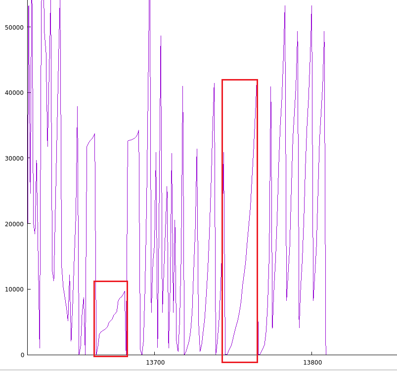
The RPM is straight forward, it’s just the RPM value and ranges from 0 to 9500 rpm, with some more granularity where the factory tuners would have wanted more control:
doi@krntija:~/targets/696/firmware$ dd if=flashdump.bin bs=1 count=60 skip=$((0x6a5d)) | xxd -p -c 60| cat | perl -pe 's/(....)/hex($1)."\n"/ge'
60+0 records in
60+0 records out
60 bytes copied, 0.000441703 s, 136 kB/s
0
1000
1300
1600
1800
2000
2400
2800
3150
3400
3700
3900
4100
4300
4600
4800
5300
5500
5800
6100
6450
6700
7000
7300
7600
8150
8500
9000
9250
9500
The TPS break points need to be decoded, however. Here’s the TPS break point data in hex:
doi@krntija:~/targets/696/firmware$ dd if=flashdump.bin bs=1 count=40 skip=$((0x6b64)) | xxd
00000000: 0000 0200 0400 0600 0a00 0e07 1161 14c5  .............a..
00000010: 1961 1f61 2948 3007 3798 4348 4d98 581f  .a.a)H0.7.CHM.X.
00000020: 68c5 7961 8cc5 a200                      h.ya....
The first two values are going to be zero and one percent throttle opening. If we divide each value by 512 (0x200) we get the percentage value:
0
1
2
3
5
7
8
10
12
15
20
24
27
33
38
44
52
60
70
81
Unsurprisingly, this looks very similar to other Ducati ECU.
Loading Data into the New ECU
I used the break points from the previous section to stuff the ignition map and fuel map into the MaxxECU.
I carved out the ignition and fuel table found in the previous section from the original firmware, remembering to double the count for the fuel map since it’s using 16-bit values, then converting to a decimal table that can be copy-pasted around:
doi@krntija:~/targets/696/firmware$ dd if=flashdump.bin of=ignition.bin bs=1 skip=$((0x7004)) count=$((20*30))
600+0 records in
600+0 records out
600 bytes copied, 0.00416472 s, 144 kB/s
doi@krntija:~/targets/696/firmware$ dd if=flashdump.bin of=fuelmap.bin bs=1 skip=$((0xA000)) count=$((20*30*2))
1200+0 records in
1200+0 records out
1200 bytes (1.2 kB, 1.2 KiB) copied, 0.00517405 s, 232 kB/s
We need to do some massaging to get this data in the right format. Namingly, RPM on the X axis, TPS on the Y axis. I used a combination of perl, awk, sed and rs to rearrange the data into the right order. It would be easy enough to write a little python script or something similar to read the data directly from the bin files above and output whatever format you want. I’m doing it this way since I’m still processing some “I used to be a unix sysadmin” emotional damage.
doi@krntija:~/targets/696/firmware$ xxd -c 20 -p ignition.bin  | perl -pe 's/(..)/hex($1)." "/ge; s/\s$//' | rs -T -C, | tac | tee ignition.csv
102,102,103,107,109,115,124,132,132,132,137,137,137,145,156,152,143,143,145,143,148,147,145,145,148,154,151,156,148,135,
102,102,103,107,109,115,124,132,132,132,130,130,130,139,145,141,139,143,139,139,141,143,145,145,143,147,147,147,149,134,
102,102,103,107,109,115,124,132,132,128,128,124,128,128,128,134,141,141,134,141,145,141,141,141,141,137,147,149,147,147,
...yoink...
doi@krntija:~/targets/696/firmware$ xxd -c 40 -p fuelmap.bin  | perl -pe 's/(....)/hex($1)." "/ge; s/\s$//' | rs -T -C, | tac | awk -F, '{for(i=NF;i>1;i--)printf "%s,",$i;printf "%s",$1;print ""}' | sed 's/^,//g' | tee fuelmap.csv
26771,26771,26970,27098,27360,27296,25715,25453,25779,26112,25056,23738,22349,21491,21491,21299,23008,23802,23738,23341,23341,23667,21126,21997,18509,16787,16787,16787,16787,20147
27034,26771,26771,27098,27629,27494,25914,25120,25651,26042,24723,23277,22086,21299,20851,20915,22323,23085,23341,23008,19373,19590,21286,21210,21210,19238,19238,19238,19238,19238
...yoink...
These then went into the greatest hacker tool of all time, a spreadsheet. I apply the multiplication factors for the ignition table, and pick a value that gives me “reasonable” VE numbers for the fuel table:
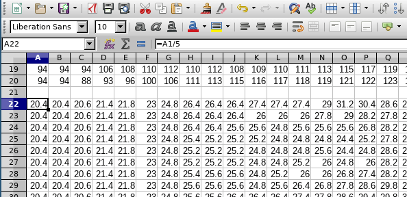
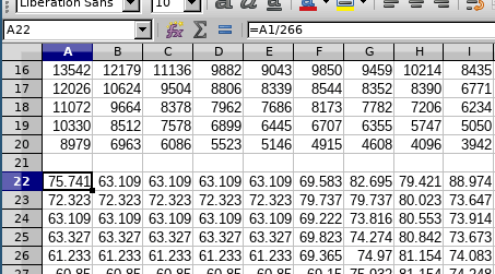
The scaling factor (266) for the fuel table above is based on publicly available dyno information for the Monster 696. We know (sort of) that the bike makes 66ish horsepower at-the-wheel at 8100 RPMish and since we know the other engine data, we can plug in values into a VE/HP estimator and twiddle the airflow numbers until the HP numbers match what we want:
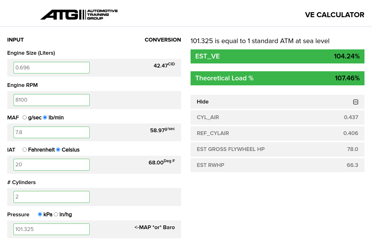
We can then divide the largest number in the fuel map by 104 to get the scaling factor. This isn’t particularly accurate, and there are many many factors that could throw this estimate out. I’m okay with this, since the fuel map will need to be tuned regardless of if I start with some clever value or a simple wedge-shaped fuel map.
Volumetric Efficiency: The ratio of air/fuel mixture drawn into a cylinder during the intake stroke compared with the volume of the cylinder. A VE of 100% means the cylinder is completely filled with air/fuel mixture. A since exhaust gas and intake air/fuel mixture have mass, the kinetic energy in those fluids can be exploited through engineered exhaust and intake systems to over-fill the cylinder, allowing for VE values of >100% in a naturally aspirated engine (an engine without a turbo or supercharger forcing more air into the engine).
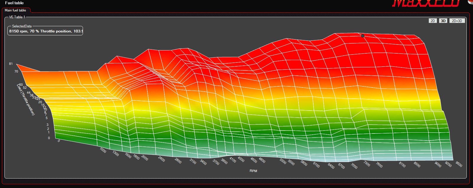
I loaded these into MaxxECU after manually setting the column/row keys based on the TPS and RPM keys, which was a little tedious since every key must be set manually if you want anything that’s non-linear. The peak volumetric efficiency seems to happen where the dyno charts suggest peak power occurs, which is somewhat reassuring:
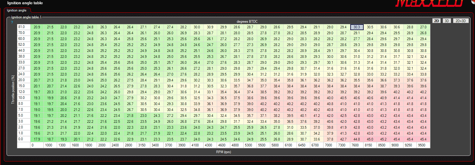
And the ignition table:
As I was tuning the bike, peak fuel load ended up at around 108/110% VE at 8500RPM. This is one of the reasons I wanted to keep the stock airbox and just swap out the ECU before making other modifications. Is the increase due to inaccurate fuel map scaling estimation on my part, ECU algorithm discrepancy, or due to a restrictive stock airbox being removed and replaced with velocity stacks?
I also ended up rescaling the fuel and ignition map down to 20x19 to get an even split of RPM from 1000 to 10,000 rpm. For my application, dealing with 20x30 maps for fuel and ignition was annoying, thus I opted for a smaller map and leaning more on cell interpolation to fill in the gaps. As I rode the bike around, I found myself wanting more control over the 3000-5000 rpm range to really dial in the part-throttle cruise. Funnily enough, this is where the factory ECU had more granularity. I might have been better off sticking with the 20x30 map dimensions and factory break points!
Summary
So, did it all work out in the end? Indeed, it did! The fuel maps needed some tuning to reach the air/fuel ratio targets I was after. Most of the fuel map was within 4-5%, except for low rpm low-throttle areas, which were very rich. These are areas that are normally adjusted on-the-fly by the factory ECU using the narrow band sensors in the exhaust system, so it makes sense they’d tune this fat by default and use the narrow-band algorithm to pull fuel out, rather than start dangerously lean and add fuel in.
The ignition map worked just fine, and any changes in there were in the pursuit of more power or smoother running in certain ranges.
I’ve since put about 3000 km on this bike with the MaxxECU running the show and it works great. The fuel and ignition tables look a little different as I’ve been refining things, but having the starting points helped get the bike up and running quicker.
Having robust data logging running all the time has been an unexpectedly powerful tool. Did I just feel the clutch slip? Don’t have to guess, I can check the logs!
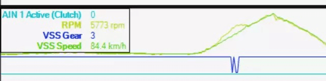
The log above shows the RPM increasing at a different rate to the vehicle speed, confirming the clutch slip. Since the current gear calculation is done based on RPM and vehicle speed, we see that confusion in the log too.
Hopefully you have found this interesting. There are a few other interesting reversing stories around this bike, and I’m looking forward to sharing some of them at Kawaiicon this year (https://kawaiicon.org/talks/vehicle-RE/).