This article takes a look at reversing the CANBUS on a Ducati Monster 696. The goal is to figure out the protocols in use and allow an aftermarket ECU to play nice with the OEM systems.
First and foremost, a safety warning. Messing with vehicles is dangerous, may void your warranty and can lead to people getting hurt. Please exercise caution and accept that this article is intended only to tell you a story of how I approached this problem. With that out of the way…
After spending far, far too much time replacing and tuning the suspension on a Ducati Monster 696, time came to handle the engine management system and try make the bike run a little better. The usual way I’d tackle this is to reverse engineer the stock ECU firmware and re-flash, tweaking the various parameters. The Siemens ECU in these bikes is based on an S12X chip with the BDM interface enabled, so extracting the firmware for analysis wasn’t particularly challenging.
Part way through digging through the firmware with Ghidra I stopped to consider what I was doing with my life.
Re-flashing the stock ECU is tedious and doesn’t give me any of the other features I’d like to see in a performance-oriented setup. No data-logging or wideband O2 controller or easy-tweakability. My solution was to junk the stock computer and replace it with a MaxxECU Street. Though, you could likely use any ECU that supports user-configurable CAN messaging (are you reading this, Haltech?)
The problem now is figuring the communication between the stock ECU and the dashboard so I can configure the MaxxECU to send the dash the data it expects to see. This isn’t my first rodeo with Ducati and their CANBUS messaging. There is another article on this site where I decide to try talk to a Ducati 848.
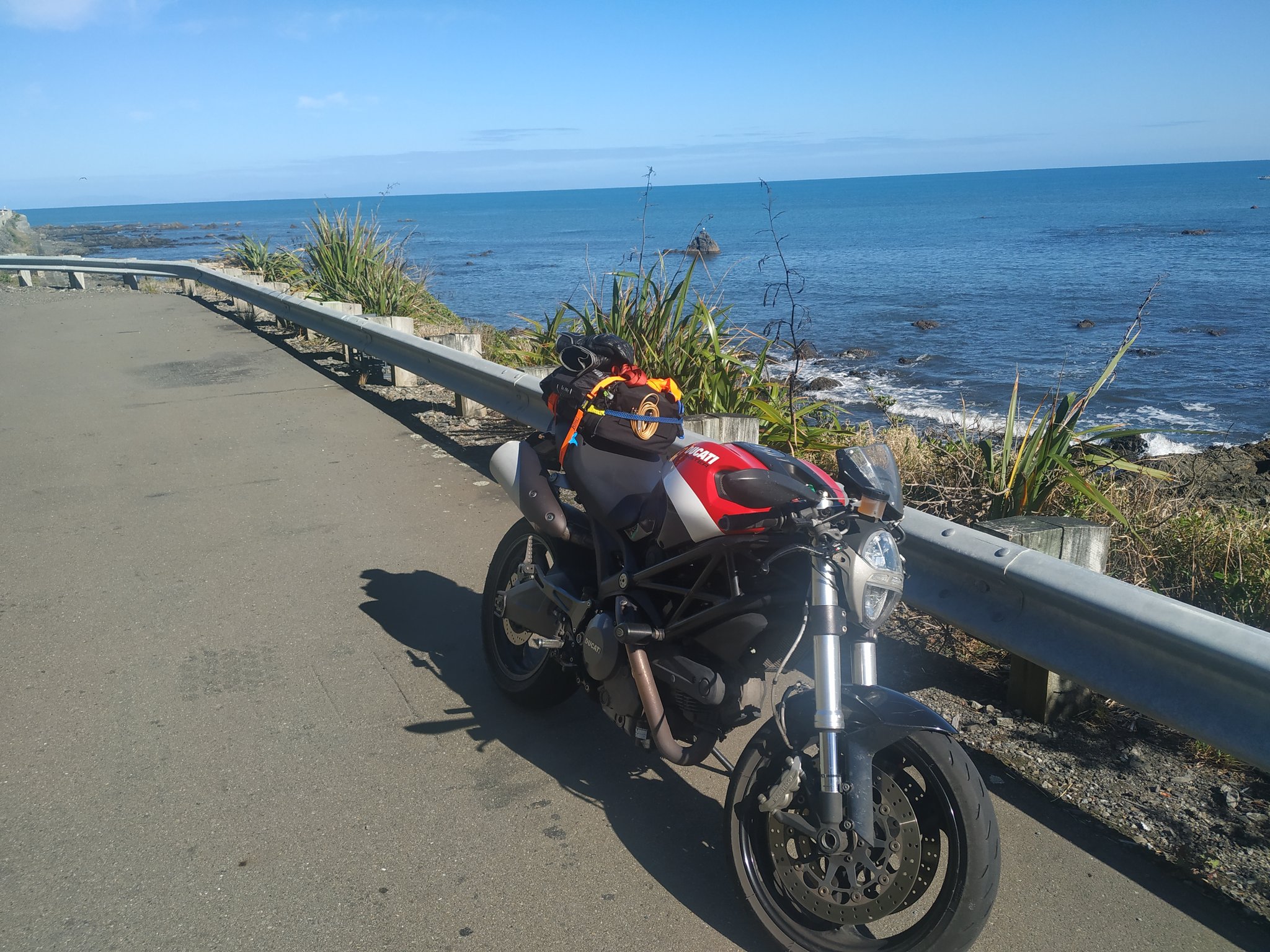
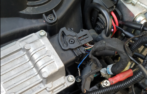
Here is our target, shown here prepped for a trek across the north island:
The Setup
The setup is very much the same as in the 848 article. We’ll be using the following hardware, all very much in the cheap-and-cheerful category:
- Hantek 6022BL oscilloscope
- Korlan USB2CAN adapter
Software wise, everything in this article was done in an Ubuntu KVM virtual machine with the USB devices passed through.
Begin - Figuring Out Communications
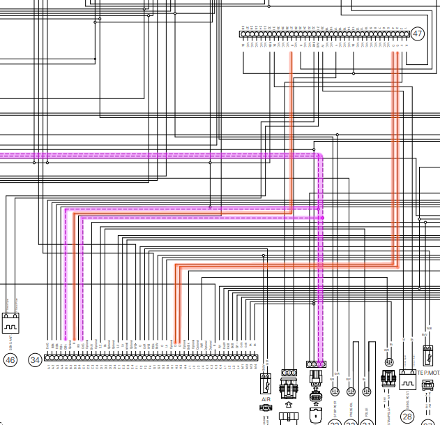
Given my previous work on Ducati CANBUS messaging, I already had some idea of how the bike was strung together. I started with the Ducati wiring diagram, which you can find on the Ducati web site in the owner’s manual for the bike. I’ve spent a few Saturday nights (because I know how to party) downloading wiring diagrams for various bikes over the years and trying to figure out where each sensor goes.
I highlighted the lines between the dashboard and the ECU:
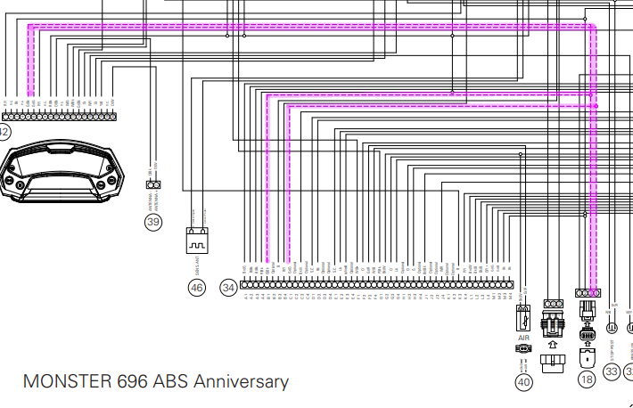
Great, looks like the bike has a single CANBUS and the diagnostic port under the seat lives on that bus. The next step was to trace each sensor and figure out if it goes to the dash or the ECU. I printed off the wiring diagram and highlighted the lines while watching cartoons.
Back to the CANBUS. Ducati don’t use standard ODB-2 connectors, so we need an adapter and can then plug in the USB2CAN device:
CANBUS Basics
CANBUS is a low-level protocol designed to allow various microcontrollers to communicate with each other. If you’re on the bus, you can read and transmit messages. There aren’t any low-level security measures such as authentication or encryption built into the CANBUS protocol, these sorts of things are left to users to implement.
In this case, Ducati is using basic CANBUS frames (not extended frames) with 11-bit message identifiers and 8-bytes worth of data per message. Kvaser have a good write-up on further CANBUS fundamentals.
Since we’re using linux’s SocketCAN drivers, we don’t really need to worry about the super low-level specifics of the CANBUS protocol for now. We can think in terms of message-IDs and data, and you’ll be able to use a bunch of the usual *nix networking tools (like ip and tcpdump) to interact with the network.
I’d suggest reading the Adventures with the Ducati CANBUS article if you haven’t already. Aside from that, what you need to know is that CANBUS has various ‘message IDs’ and data associated with those IDs. For example, I might write something like:
#define FRAME_SENSORDATA1 0x041
And then send all my various sensor information using CANBUS message ID 0x041. The other microcontrollers would read this and understand that messages read from the bus with ID 0x041 contain sensor information, and then extract the data from the data bytes accordingly.
Capturing Data
After plugging in, I set the bit rate and run a quick test to make sure I can capture data:
root@buzdovan:~# ip link set can0 type can bitrate 500000
root@buzdovan:~# ip link set can0 up
root@buzdovan:~# candump can0
...key on...
  can0  080   [8]  00 00 00 00 00 00 00 00
  can0  081   [8]  00 00 00 00 00 00 00 00
  can0  080   [8]  00 00 00 00 00 00 00 00
  can0  081   [8]  00 00 00 00 00 00 00 00
  can0  080   [8]  00 00 00 00 00 00 00 00
  can0  081   [8]  00 00 00 00 00 00 00 00
  can0  080   [8]  00 00 00 00 00 00 00 00
  can0  081   [8]  00 00 00 00 00 00 00 00
  can0  080   [8]  00 00 00 00 00 00 00 00
  can0  081   [8]  00 00 00 00 00 00 00 00
This bus uses a 500kbit network. There is a section in the Adventures with the Ducati CANBUS article on figuring out the data rate.
SocketCAN support in Linux means we can use tcpdump and Wireshark for logging all the packets:
root@buzdovan:~# tcpdump -i can0
tcpdump: verbose output suppressed, use -v or -vv for full protocol decode
listening on can0, link-type LINUX_SLL (Linux cooked), capture size 262144 bytes
...key on...
13:36:35.913991
    0x0000:  8000 0000 0800 0000 0000 0000 0000 0000  ................
13:36:35.914272
    0x0000:  8100 0000 0800 0000 0000 0000 0000 0000  ................
13:36:35.914692
    0x0000:  1000 0000 0800 0000 c800 0000 0000 0000  ................
13:36:35.914942
    0x0000:  2000 0000 0800 0000 0000 404f a100 0000  ..........@O....
13:36:35.915189
    0x0000:  2800 0000 0800 0000 0000 0000 0000 0000  (...............
13:36:35.915449
    0x0000:  0003 0000 0800 0000 0b00 621e 0000 0000  ..........b.....
13:36:35.915691
    0x0000:  2900 0000 0800 0000 0000 0000 0000 0000  )...............
13:36:35.917865
    0x0000:  8000 0000 0800 0000 0000 0000 0000 0000  ................
13:36:35.918088
Let’s look at the output from tcpdump a little closer, it’ll make the rest of this post make a little more sense:
 0x0000:  8100 0000 0800 0000 [0000 0000 0000 0000]
 0x0000:  [8100 0000] [08][00 0000] [0000 0000 0000 0000]
                │       │       │             │
                │       └─────┐ └────────┐    └───────┐
                │             │          │            │
Message Identifier & Flags   Length    Reserved    Data Bytes
Alternatively, you can use the candump command from the can-utils package. This spits out log files that can be subsequently replayed with can-player, which is a handy trick. The following figure shows the candump command and subsequent output:
$ candump -l can0
Disabled standard output while logging.
Enabling Logfile 'candump-2021-08-19_161242.log'
^C
doi@doi-Standard-PC-Q35-ICH9-2009:~/candumps$ head candump-2021-08-19_161242.log
(1629346373.166675) can0 080#0000000000000000
(1629346373.166684) can0 081#0000000000000000
(1629346373.172325) can0 080#0000000000000000
(1629346373.172330) can0 081#0000000000000000
(1629346373.176905) can0 080#0000000000000000
                        [081]#[0000000000000000]
                         ID          Data
We’ll use a combination of both in this post; use whatever works for you.
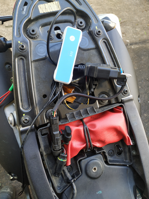
Next, I had to determine which messages were created by the ECU (these we would have to replicate) and which messages were being generated by the dashboard. Going back to the wiring diagram, we see two constantly-on fuses, one labeled ECU and one labeled Dash:
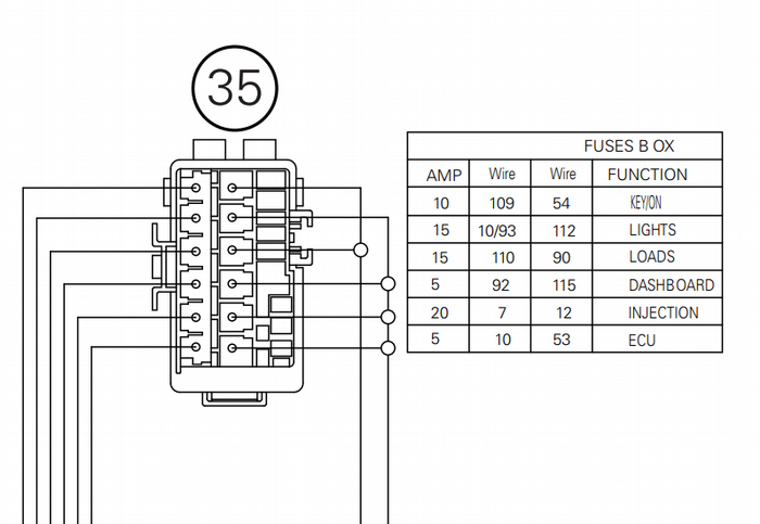
Here’s the respective fuse set on the bike:
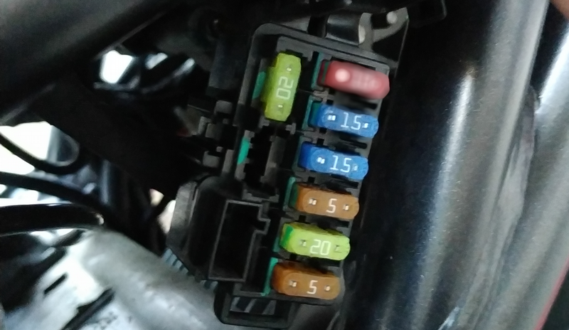
Both the dash and the ECU took a constant 12v supply from their respective fuses, and then another switched 12v. I was hoping that pulling the fuse would prevent the dash or the ECU from powering on even when the key was on. This was the case for the ECU, the dashboard however happily kept transmitting with its fuse pulled (albeit with no LCD display activity). Rats.
The next step was to unbolt the head fairing and physically unplug the dashboard:
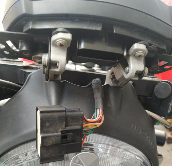
After running another set of captures, one with the dash unplugged and the other with the ECU powered off, we can confirm which messages originated from the ECU, and which came from the dashboard:
| ID | Origin | Send Interval |
|---|---|---|
0x10 |
Dash | 5ms |
0x20 |
Dash | 20ms |
0x28 |
Dash | 20ms |
0x29 |
Dash | 100ms |
0x80 |
ECU | 5ms |
0x81 |
ECU | 5ms |
0x100 |
ECU | 20ms |
0x201 |
ECU | 100ms |
0x211 |
ECU | 100ms |
0x280 |
ECU | 100ms |
0x290 |
ECU | 100ms |
0x300 |
Dash | 100ms |
So far, the engine has just been started and run with the bike stationary. We need a more complete run-log. I chocked the front, raised the rear wheel on a stand and ran it in first gear while grabbing a pcap:
doi@buzdovan:~/targets/696$ sudo tcpdump -w run1.pcap -i can0
tcpdump: listening on can0, link-type LINUX_SLL (Linux cooked), capture size 262144 bytes
^C31985 packets captured
32375 packets received by filter
0 packets dropped by kernel
You could get an even more complete log file by using a Raspberry PI with a PICAN2 board and going for a ride, but the above is good enough for me for now.
The next step is to determine what the data in each of the ECU-originated messages means. While we can dig into the dashboard-originated messages a bit more when we start implementing things like immobilizers in the new ECU, this article will be focusing on the ECU-originated messages.
Analysis - PCAPs For All
I generally break the analysis portion up into two discrete sections: reviewing logs and active analysis/injection. Let’s start by reviewing what’s in our logs so far, since this can be done from a cushy office chair rather than the workshop. My approach for the log analysis was - look at each message id, try figure it out, move onto the next one.
We have seven message IDs which are sent by the ECU. Some easy wins first…
Messages 0x280 and 0x290
0x280 and 0x290. These correspond to the start-up message displayed on the dashboard:
doi@buzdovan:~/targets/696$ sudo tcpdump -r start-stop.pcap
...snip...
12:10:43.332768
    0x0000:  8002 0000 0800 0000 2020 4d4f 4e53 5445  ..........MONSTE
12:10:43.333957
    0x0000:  9002 0000 0800 0000 5220 3639 3620 2020  ........R.696...
...snip...
Easy, 16 bytes of ASCII data split across two messages. That’s two down, five to go. (or so I thought! Does this sound like…. foreshadowing? Yes. Yes it does.)
Message 0x201
In all logs so far, 0x201 is always just nulls:
doi@buzdovan:~/targets/696$ /sbin/tcpdump -r run1.pcap | grep ":  0102" | uniq
reading from file run1.pcap, link-type LINUX_SLL (Linux cooked)
    0x0000:  0102 0000 0800 0000 0000 0000 0000 0000  ................
That’s another one down, four to go. Let’s look at the high-frequency messages next (0x080 and 0x081).
Messages 0x80 and 0x81
This is where uniq is particularly powerful. Since these messages are transmitting every 5ms, they often contain the same data across multiple consecutive messages. By piping this through uniq, we can see just the messages that have data that’s, well… unique. Take a look:
doi@buzdovan:~/targets/696$ /sbin/tcpdump -r run1.pcap | grep ":  8000" | wc -l
reading from file run1.pcap, link-type LINUX_SLL (Linux cooked)
8300
doi@buzdovan:~/targets/696$ /sbin/tcpdump -r run1.pcap | grep ":  8000" | uniq | wc -l
reading from file run1.pcap, link-type LINUX_SLL (Linux cooked)
51
For a brief run on the stand, we got 8300 0x080 messages. Uniquing them down gives us 51, much more digestible. After digging into 0x080 messages across both the key-on-no-start and the start-and-run logs, I can see one byte changing, which seems to correlate with throttle position:
doi@buzdovan:~/targets/696$ /sbin/tcpdump -r run1.pcap | grep ":  8000" | uniq
reading from file run1.pcap, link-type LINUX_SLL (Linux cooked)
    0x0000:  8000 0000 0800 0000 0000 0000 0000 0000  ................
    0x0000:  8000 0000 0800 0000 0000 0000 0200 0000  ................
    0x0000:  8000 0000 0800 0000 0000 0000 0400 0000  ................
    0x0000:  8000 0000 0800 0000 0000 0000 0600 0000  ................
All other bytes remain at 0x00, we can confirm this with cansniffer shortly. Let’s look at 0x81 next:
doi@buzdovan:~/targets/696$ /sbin/tcpdump -r nostart.pcap | grep ":  8100" | uniq
reading from file nostart.pcap, link-type LINUX_SLL (Linux cooked)
    0x0000:  8100 0000 0800 0000 0000 0000 0000 0000  ................
    0x0000:  8100 0000 0800 0000 0000 06f9 0000 0000  ................
    0x0000:  8100 0000 0800 0000 0000 0000 0000 0000  ................
    0x0000:  8100 0000 0800 0000 0100 0000 0000 0000  ................
doi@buzdovan:~/targets/696$ /sbin/tcpdump -r run1.pcap | grep ":  8100" | uniq | wc -l
reading from file run1.pcap, link-type LINUX_SLL (Linux cooked)
1179
0x081 is significantly more active. Looking at the message from the no-start log, we can see how many instances of each message there are:
doi@buzdovan:~/targets/696$ /sbin/tcpdump -r nostart.pcap | grep ":  8100" | uniq -c
reading from file nostart.pcap, link-type LINUX_SLL (Linux cooked)
      7     0x0000:  8100 0000 0800 0000 0000 0000 0000 0000  ................
      4     0x0000:  8100 0000 0800 0000 0000 06f9 0000 0000  ................
    620     0x0000:  8100 0000 0800 0000 0000 0000 0000 0000  ................
   5680     0x0000:  8100 0000 0800 0000 0100 0000 0000 0000  ................
What I’d like to see is what data is changing, let’s unique the last four bytes of the messages and see if they change across our log files:
doi@buzdovan:~/targets/696$ /sbin/tcpdump -r run1.pcap | grep ":  8100" | awk '{print $8,$9}' | uniq
reading from file run1.pcap, link-type LINUX_SLL (Linux cooked)
0000 0000
doi@buzdovan:~/targets/696$ /sbin/tcpdump -r nostart.pcap | grep ":  8100" | awk '{print $8,$9}' | uniq
reading from file nostart.pcap, link-type LINUX_SLL (Linux cooked)
0000 0000
Of the 8 bytes in that message, so far bytes 5, 6, 7 and 8 have been always set to 0x00. Sorting and grouping by the first two bytes, we can see the following:
doi@buzdovan:~/targets/696$ /sbin/tcpdump -r run1.pcap | grep ":  8100" | awk '{print $6}'  | sort | uniq -c
reading from file run1.pcap, link-type LINUX_SLL (Linux cooked)
    175 0000
     52 0001
   2754 0100
   3577 0101
     20 0201
    314 0301
     14 0401
    614 0601
    520 0801
    260 0a01
doi@buzdovan:~/targets/696$ /sbin/tcpdump -r nostart.pcap | grep ":  8100" | awk '{print $6}'  | sort | uniq -c
reading from file nostart.pcap, link-type LINUX_SLL (Linux cooked)
    631 0000
   5680 0100
Byte 2 is always either 0 or 1, which is interesting. Let’s remove the sort statement and look at these bytes over time:
doi@buzdovan:~/targets/696$ /sbin/tcpdump -r run1.pcap | grep ":  8100" | awk '{print $6}'  | uniq -c
reading from file run1.pcap, link-type LINUX_SLL (Linux cooked)
    349 0100
    175 0000
    675 0100
    995 0101
    314 0301
     18 0201
     12 0401
    582 0601
      2 0801
...snip...
Byte 2 seems to stay as 0x01 while the engine is running. Byte 1 increases, then floats between 0x08 and 0x0a then settles back down to 0x01. Interesting. Looking closer, byte 1 corresponds to the throttle position, similarly to message 0x80:
        0x0000:  8000 0000 0800 0000 0000 0000 [04]00 0000  ................
        0x0000:  8100 0000 0800 0000 [04]01 0356 0000 0000  ...........V....
        0x0000:  8000 0000 0800 0000 0000 0000 [04]00 0000  ................
        0x0000:  8100 0000 0800 0000 [04]01 0356 0000 0000  ...........V....
        0x0000:  8000 0000 0800 0000 0000 0000 [06]00 0000  ................
        0x0000:  8100 0000 0800 0000 [06]01 0356 0000 0000  ...........V....
This leaves bytes 3 and 4:
doi@buzdovan:~/targets/696$ /sbin/tcpdump -r run1.pcap | grep ":  8100" | awk '{print $7}'  | uniq -c
reading from file run1.pcap, link-type LINUX_SLL (Linux cooked)
    352 0000
      4 06f9
   1088 0000
      4 06f9
      4 031d
      4 03d9
      4 0000
      4 0451
      4 0000
      4 03df
      4 0358
      4 0000
      4 0397
      4 03b6
      4 0000
...snip...
doi@buzdovan:~/targets/696$ /sbin/tcpdump -r nostart.pcap| grep ":  8100" | awk '{print $7}'  | uniq -c
reading from file nostart.pcap, link-type LINUX_SLL (Linux cooked)
      7 0000
      4 06f9
   6300 0000
Digging further into each byte, byte 4 ranges between 0x00 and 0x98. Byte 3 ranges between 0x00 and 0x06. This gives us the following binary values:
00 - 0000
01 - 0001
02 - 0010
03 - 0011
04 - 0101
05 - 0101
06 - 0110
Potentially three flags of some sort? Or used in conjunction with byte 4 to form a 16-bit value? Let’s note this down and come back to it.
Message 0x100
Next up, message ID 0x100. As above we can start by ruling out the bytes that never change and isolating the bits we need to investigate further. The following snippet shows an example 0x100 message, and highlights the bits that never change across the logs:
E0 0F [00] 05 5F 21 [00] 01
Byte 1 (0xE0 above) seems to be either 00, E0, or 20 in the above capture, so let’s look at byte 2 first. This byte has a bunch of different values in the run log, we can graph them and see if that sheds any insights:
doi@buzdovan:~/targets/696$ /sbin/tcpdump -r run1.pcap| grep ": 0001" | awk '{print $6}' | grep -Po '..$' | xargs -i[] printf "%d\n" 0x[] > 100-2.csv
Bytes 4 and 5 have a wide range of values too, so let’s add those as another line:
doi@buzdovan:~/targets/696$ /sbin/tcpdump -r run1.pcap| grep ":  0001" | awk '{print $6}' | grep -Po '..$' | xargs -i[] printf "%d\n" 0x[]  > 100-2.csv
doi@buzdovan:~/targets/696$ /sbin/tcpdump -r run1.pcap| grep ":  0001" | awk '{print $7,$8}' | grep -Po '.. ..' | sed 's/ //' |xargs -i[] printf "%d\n" 0x[] > 100-4-5.csv
doi@buzdovan:~/targets/696$ paste -d, 100-2.csv 100-4-5.csv > combined.csv
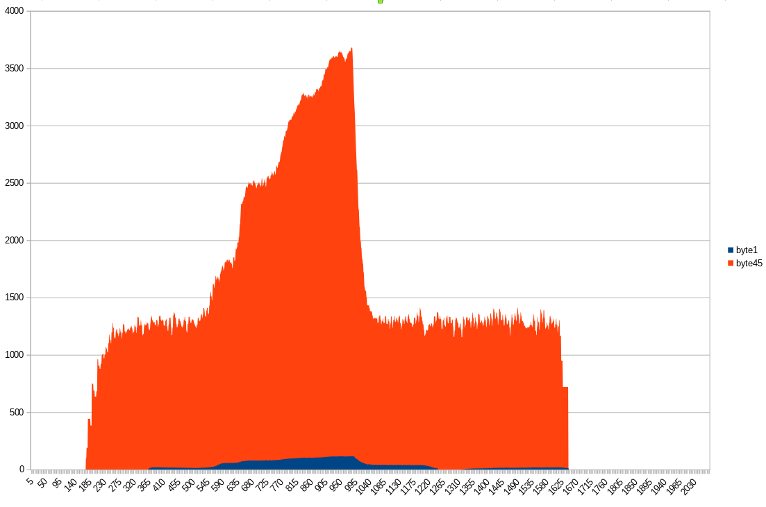
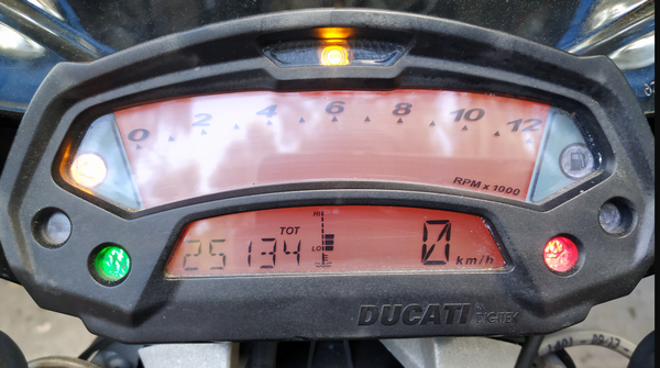
Byte 2 is vehicle speed (or, more specifically, rear-wheel speed) and byte 4-5 are the engine RPM. There is a small wrinkle here though, one byte (a max of 255) would mean our speedometer maxes out at 255km/h (it doesn’t…) or has to change in increments of >1km/h (also doesn’t…). Our remaining bytes seem to be flags, which we will look at closer in the next section. You can probably start getting an idea for how CANBUS reversing can be used to harvest data that’s useful for data logging and analysis.
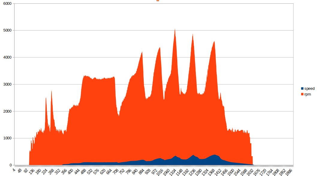
Here is another graph, parsed out from candump output of the bike running through all six gears:
Message 0x211
And finally, message 0x211. Here is an example of the data:
4e88 0037 d300 0000
Byte 4 is the air temperature displayed on the dash, plus 40 (in degrees Celsius). Here we have 0x37, so 55-40 == 15 or 15 degrees Celsius, which lines up with what was on the dashboard at the time of logging. The null bytes above remained null throughout the no-start and run logs, we’ll dig into them a bit more in the next section too. I suspect that first byte is the engine temperature, the sensor for which lives on the vertical cylinder.
Log Analysis - Summary
Right, let’s review. We’ve “figured out” message IDs 0x80, 0x201, 0x280, 0x290, and still have questions about parts of 0x81, 0x100, and 0x211. Specifically, the bytes highlighted below:
0x081   0401 [0241] 0000 0000
0x100  [e0]12 0004 d7[21] 00[01]
0x211  [4ea2] 0036 [d3]00 0000
Rather than continue to pour over PCAPs we can start to take a more active approach.
Analysis - Active Logging
So far, we have just looked at logs and tried to make sense of the data we’re seeing. The analysis work can be made easier by triggering certain functions such as pulling the bike into and out of neutral to trigger the neutral light, and then seeing what changes on the CANBUS. This will hopefully make sense of a few of the grey areas from the previous section.
All of the following terminal outputs are from the cansniffer can0 command. The first one is easy, turn the key on and roll the throttle back and forth:
0xC8 or 200 at full throttle in byte 5 of 0x080 and byte 1 of 0x081. I’d expect a percentage here, so let’s look at all of the data we have for that byte value across a run (this time with candump logs):
$ grep -h '080#' candump-2021-08-19_1*  | awk '{print $3}' | perl -pe 's/...#00000000(..).*/$1/' | sort -u
00
02
04
06
08
0A
0C
0E
10
12
14
16
18
1A
1C
1E
20
22
24
The least significant bit was never set on this byte. Given that the same value is in byte 1 in 0x081, I’m going to assume that throttle position is a 7-bit integer. Why would they do this? Well let’s look at the clutch next.
The clutch switch goes to the ECU - see what happens when we pull the clutch with the engine running:
The clutch is the least-significant bit in 0x081 byte 1, which makes the throttle position 7-bit integer make a little more sense.
Next, I’ll look at the kill-switch on the right handlebar. The wiring diagram shows this going to the ECU too:
Aha! Kill-switch corresponds to the last bit in byte 8, in message 0x100. Let’s try the neutral light next:
0xE0 is a strange value. This corresponds to 1110 0000 in binary. Let’s capture another log, running through all six gears and see what the values are. This run had a bonus, in that I managed to make the neutral light turn off while it wasn’t in gear.
Ducati have notoriously unreliable neutral switches, so it’ll be interesting to see how the ECU handles that condition:
100#E0
100#00
100#E0
100#20
100#40
100#60
100#80
100#A0
100#80
100#81
100#80
100#A0
100#E0
100#00
When the neutral light is off but the ECU cannot detect what gear the engine is in (by cross-referencing vehicle speed and RPM) the value is 0xE0. The first 3 bits set what gear the bike is in, and all three are unset when the neutral switch is engaged:
Neutral     - 0x00
Error       - 0xE0
First       - 0x20
Second      - 0x40
Third       - 0x60
Fourth      - 0x80
Fifth       - 0xA0
Sixth       - 0xA0
Interesting. Guess they ran out of bits for sixth gear maybe? Or the fact that the rear wheel wasn’t spinning fast enough for it to tell what was going on accurately. Either way, the dashboard does not support a gear read-out, so at least for the purposes of installing an aftermarket ECU, this part of the analysis being vague is reasonably inconsequential.
The remaining bits in this byte are used for the vehicle speed. The issue I mentioned earlier where the vehicle speed didn’t make sense? This is why. The first byte in this message is used to communicate both the current gear, and the upper bits of the vehicle speed. For example:
100#E140000000000000
E1 41
1110 0001 0100 0000 ...
──┐- ┌─────────────
  │  │
  │  │
  │  └─ Vehicle Speed
  │
  │
  └─── Gear/Neutral
Once the new ECU is in, we will figure out the numeric output from this value versus a GPS reference to calibrate the speedometer output.
The last step before moving onto data injection is to unplug the MAP (manifold absolute pressure) sensor and see what changes. Message 0x201 springs into life and a PRESS error turns up on the dashboard. Additionally, byte 5 in message 0x211 goes to 0xFF and stays there:
201#[02]00000000000000
211#45850039[FF]000000
As per usual, about five minutes of active analysis has saved a boat load of time staring at PCAPs. Let’s update the list with the new bytes we’ve figured out:
0x81   0401 [0241] 0000 0000
0x100  e012 0004 d7[21] 0001
0x211  [4ea2] 0036 d300 0000
A more complete picture is forming.
Analysis - The Dee Dee Method
Next, we can use the tried-and-true hacker methodology of “play with it and see what happens”. Or in the words of Dee Dee from Dexter’s Lab: “oooooh what does this button do?”.
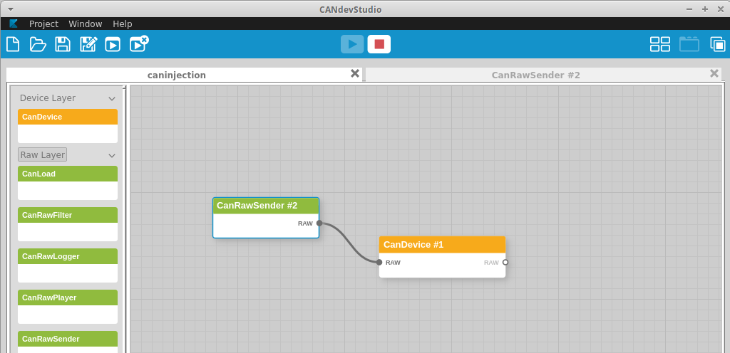
I pull the ECU fuse, and begin broadcasting some data using CANDevStudio. CANDevStudio provides a GUI for doing CANBUS reverse engineering work. The other option is to use multiple cangen commands in different terminal windows, but for demonstration purposes having everything in one window is handy.
Another handy trick is to use the cangen command to fuzz a specific message and look at what changes in the system. For instance, to fuzz the message containing temperature: cangen can0 -g 100 -I 211 -L8. This will send 8 random bytes on CAN message 0x211 every 100 milliseconds.
An important note here. Broadcasting malformed data onto the bus can have adverse effects. Be prepared to potentially damage your target systems and DO NOT perform this while driving.
Given that we’ve already figured out a decent chunk of what’s going on, we can be more targeted. First, let’s get CANDevStudio plumbed together:
We can now start tampering the values to see what happens. You’ll notice I’ve already tweaked the 0x280 and 0x290 messages in the next screenshot, which should display a new message. This is my quick check to make sure the injection is working.
Let’s start with what I suspect to be engine temperature. I’m not really worried about the specific values, since working that out will be done along with measuring the sensor against a reference thermometer to determine its resistance curve. I’m not doing that now because, honestly, that sensor is a pain to get to.
Let’s set byte 1 of 0x211 to 0xFF and observe the difference:
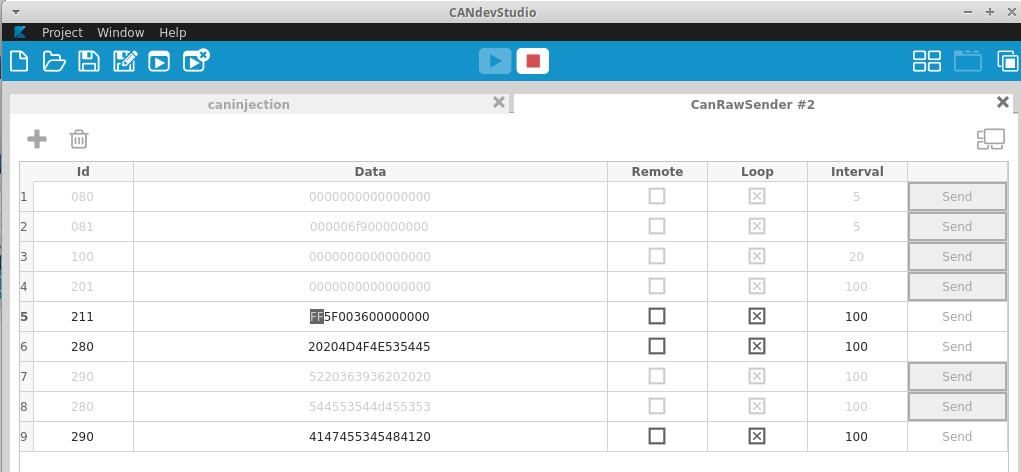
I’m making a start here by fuzzing only byte 1 in message 0x211. I figure this is the engine temp, so let’s see what happens on the dashboard:
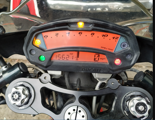
Perfect, this maxes out our engine-temp readout, confirming byte 1 is our engine temperature. You may have also noticed my bike now displays miles-per-hour… more on that soon.
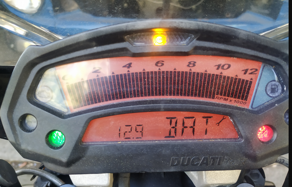
Let’s move onto the next byte. Setting byte 2 to another value and looking for change:
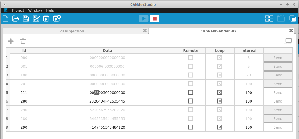
This changes the voltage readout on the display. I’ll set a few different values here and note what the changes on the dashboard are:
5F = LO
60 = 10.0
61 = 10.0
62 = 10.1
63 = 10.1
64 = 10.2
65 = 10.3
66 = 10.3
67 = 10.4
68 = 10.5
69 = 10.5
6a = 10.6
6b = 10.6
6c = 10.7
6d = 10.8
6e = 10.8
6f = 10.9
70 = 11.0
...snip...
7f = 11.9
..snip...
A2 = 14.1
..snip...
AF = 14.9
..snip...
B0 = 15.0
..snip...
BF = 15.9
..snip...
C0 = 16.0
CF = HI
Next, we have the 0x21 value in message 0x100. Setting this to 0x00 turns the ABS light off, setting it back to 0x21 turns it back on. Excellent, we should be able to program the ECU to set these bits based on the “ABS light” signal from the ABS module.
This got me thinking, what about byte 7 in that message? It was constantly at 0x00, but since we’re here we may as well check it. Setting it to 0xFF causes the shift light to flash!
Some more playing around shows the shift light is tied to the top three bits of byte 7, and we get the following functionality:
0x80 - 1000 0000 - Fast flash
0x40 - 0100 0000 - Solid
0xC0 - 1100 0000 - Slow flash
Awesome, this is going to be a good way to communicate shift points and potentially other data while tuning. Want to street tune a specific chunk of the fuel or ignition map? Maybe enable a slow flash while you’re in the target zone so you can easily be sure you’re hitting the right cells while logging. So many possibilities.
I think it’s important to note: if we had hit the rev limiter in the run log, we could have seen this in the packet captures.
Every Error
What about the remaining bits that were never set in the logs and weren’t triggered so far? We can broadcast some data and see what happens to the dash.
I decided to do this for message 0x201, which hasn’t received much love so far. Turns out this is how the stock ECU sends error message codes to the dashboard. I used the cangen command to send a message with every bit set to 1, and watched what happened:
doi@buzdovan:~/targets/696$ cangen can0 -I 201 -D FFFFFFFFFFFFFFFF -L 8 -g 100
The dashboard cycled through every error code, and also unset my service light.
Before:
And after:
Teeny wrench is gone! Luckily, I’ve actually done my 24,000km service. Who needs a factory diagnostic system when you have a CANBUS fuzzer. I wonder if this same command could be used to unset the service light on newer Ducati with the M3C Siemens ECU? Maybe some daring Ducati Scrambler or Monster 797 owner can try it and let us all know.
Chasing My Tail - Why does my bike think it’s in France?
I managed to shoot myself in the foot with this project. How? Hubris. Earlier in this article I said:
Easy, 16 bytes of ASCII data split across two messages. That’s two down, five to go.
Hmm. I sent some garbage message using CANDevStudio to make sure it would display on the dash - and it did. However, while going through the injection process, I noticed that my bike thought it was in France, displaying “FRA” on the dashboard.
Also, I now had traction control apparently:
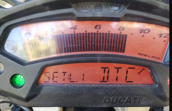
Now, I had made the assumption that 0x280 and 0x290 were only the dashboard message string and proceeded to spend hours with canplayer, doctoring messages to see what was responsible for this happening. I thought maybe those unknown bits in 0x081 were somehow communicating DTC status and not sending them at the right time was causing the dash to think I had traction control?
Turns out all of this was wrong. This byte right here:
doi@buzdovan:~/targets/696$ sudo tcpdump -r start-stop.pcap
...snip...
12:10:43.333957
        0x0000:  9002 0000 0800 0000 5220 3639 3620 20[20]  ........R.696...
...snip...
That byte is not an ASCII space character. It’s a bit field that sets the bikes locale and features. 0x20 means EU with no DTC, apparently.
Witness my suffering. Assume nothing.
The end result - A spec… sort of…
Putting all of this information together, we get a list of messages and what they’re used for:
     080#00000000C8000000
         - - - - │ - - -
            ┌────┘
            │
     Throttle position


     081#C901000000000000
         │ │ ───┐- - - -
         │ │    └────── ??  - Linked to VSS
         │ └──Run
      1100 1001───Clutch
      ────────
        TPS

     100#E0040005DC210001
         ┌───- │   │ │ │
         │     │   │ │ │
         │     │   │ │ └─Killswitch on/off
         │    RPM  │ │
         │         │ └──Shift light
     VSS + Gear    │    0xC0 Slow
         │         │    0x80 Fast
         │         │    0x40 Solid
         │         │
         │         └────ABS Light
         │
     1110 0000 0000 0100
     ───-───────────────
     Gear  Vehicle Speed

     201#0000000000000000
         Error code bits - Further analysis needed
         Set all bytes to 0xFF for a quick/dirty service reset

     211#4E880037d4000000
         │ │ - │ │ - - -
         │ │   │ └─────Air pressure?
         │ └┐  │
Engine temp │  └─────┐
           Volts     │
                    Ambient temp

     280#4141414141414141
         Start Message - first 8

     290#4141414141414120
         ────┬─────────-
             │         │
  Start message, last 7│
                       └───Locale + features
We now have enough data to configure our new ECU to drive the dashboard, fantastic!
EDIT: Some more digging while configuring the MaxxECU ended up revealing more information regarding the ABS light flag, set as 0x21 above. These are really three flags as below:
0x21 - 0010 0001
       │ │     │
       │ │     └───Run
       │ │
       │ └─────────ABS Light
       │
       └───────────Starter button
The starter button flag is helpful, since it causes the dashboard to temporarily disable the headlight while the engine is cranking.
CANBUS Reversing - Summary
We’ve learned a bunch about the Ducati CANBUS; however, we don’t know everything. There are still some mysterious bits (0x081 bytes 2-4, for example) that I don’t completely understand. For my purposes though, we’re in a good position right now. For the packet log analysis especially, having a non-complete log put me at a disadvantage. I’d recommend attaching a CANBUS interface and logging all conditions, such as rev-limiters being hit, shift lights being hit and error codes.
If I had to summarise my methodology for this run through, it would be:
- Gain access to the CANBUS in a stock configuration and begin logging.
- Determine which micro-controller is responsible for sending each message.
- Diff byte values per-message under different conditions and observe changes.
- Review the logs and see if any items make obvious sense.
- Use something like
cansnifferto observe the bus while using the various systems and document the changes. - Inject CANBUS messages with tampered values and observe for changes, documenting outcomes.
This is all quick-win stuff and can happen fairly quickly. A complete, thorough review would involve dumping the firmware of both the dashboard and the ECU and disassembling the code, finding the CANBUS logic and determining all supported features that way. This would provide a complete view, but naturally is significantly more time-consuming. If you need a complete and perfectly accurate specification for the system, then this would be the way to go (along with completing the steps above - who doesn’t love quick wins).
ABS Module
For the new ECU to work, I also needed to figure what the deal is with the ABS module. Going back to the wiring diagram, I see three wires going from the module to the ECU:
The Ducati wiring diagram is wrong here. The pin numbers are correct, but the GREEN wire should be labeled VIOLET. Attaching a scope between each wire and ground we see the following (after turning the rear wheel by hand with the engine off):
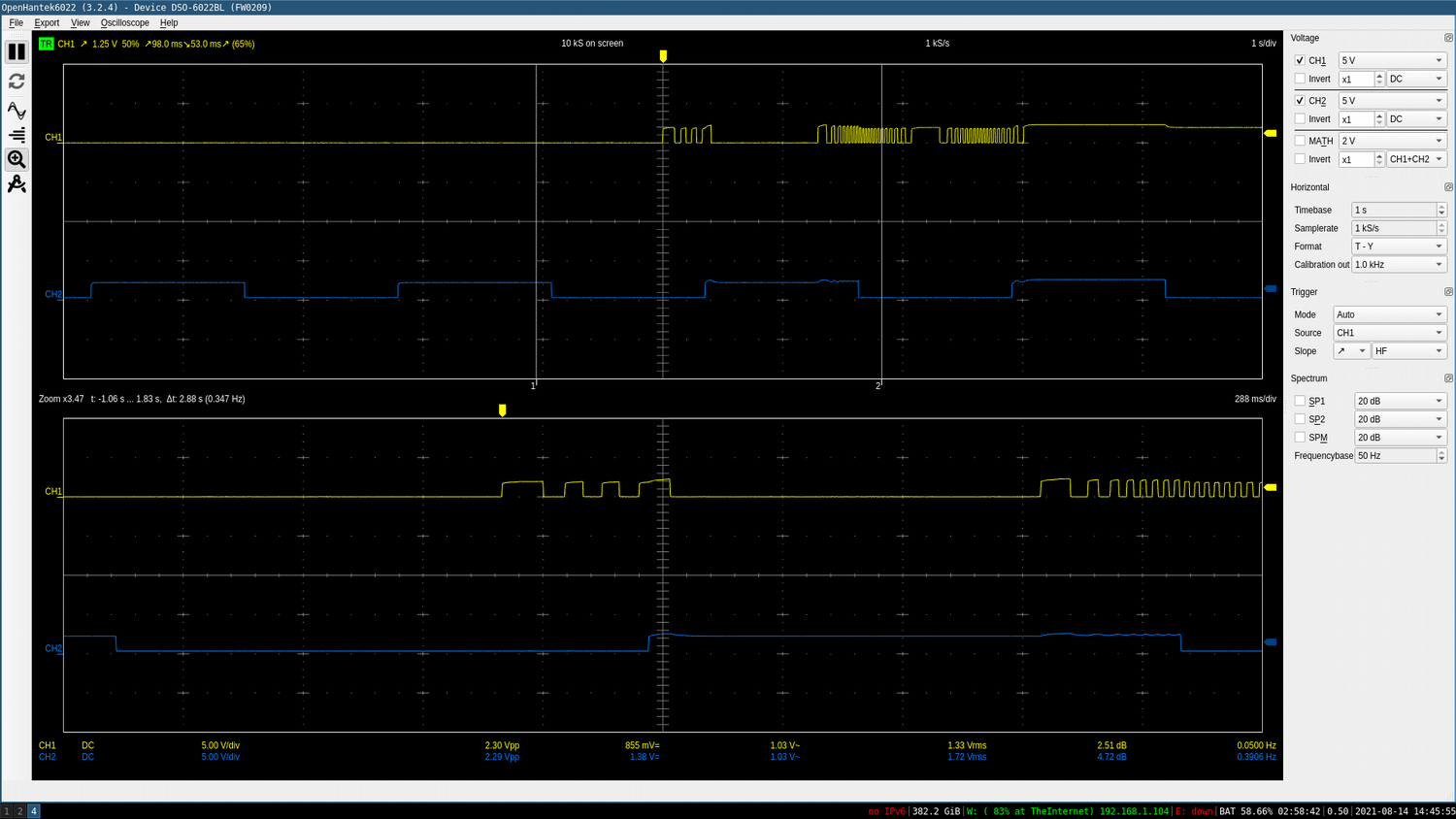
These are 2.5v logic signals. The violet wire (scope channel 1) is the vehicle speed, the orange wire (scope channel 2) is the ABS light. Here it’s flashing because I disabled the ABS via the dashboard controls.
The third wire (which was CORRECTLY labeled blue in the wiring diagram…) is a +12v signal from the ABS module. The ECU pulls this wire to ground to disable the ABS temporarily when you select the “Disable ABS” function in the dashboard. The ECU pulls the wire to ground, then goes back to +12v after a short delay. If this wire is left pulled to ground (say, by a jumper wire to the negative battery terminal…) then the ABS reactivates itself automatically.
Out of curiosity, I de-pinned the connector for the “disable” signal:
And then disabled the ABS via the dashboard. The dashboard ABS light flashed as if the ABS was deactivated even though it wasn’t. The ABS light flashing effectively means “The dashboard has requested the ABS to be disabled” not “The ABS is currently disabled”.
This is a safety issue for me when on track. I leave ABS on while riding on the road, but on a racetrack where braking is much heavier, ABS becomes a liability. ABS being enabled in this scenario when I don’t expect it to be could end up in an unexpected off-track excursion. As a result, I won’t be implementing the disable functionality in the new ECU, and instead will rely on removing the ABS fuses for racetrack duties.
Wrap-up
Hopefully you’ve found this article interesting. My goal here is to share my process and attempt to demystify some of the automotive hackery that’s possible with cheap tools. I doubt this will be the last article I write on hacking up motorcycles.
I’ve purposefully omitted wiring in and configuring the new ECU, I’ll leave explaining those details to the pros. Specifically, High Performance Academy, another set of Kiwi nerds. HPA have some great material on YouTube around how to get into motor-sports wiring and where to start, along with a wiring fundamentals course. Check them out.
Until next time.